Chapter 5 How to Operate BERT
5-16
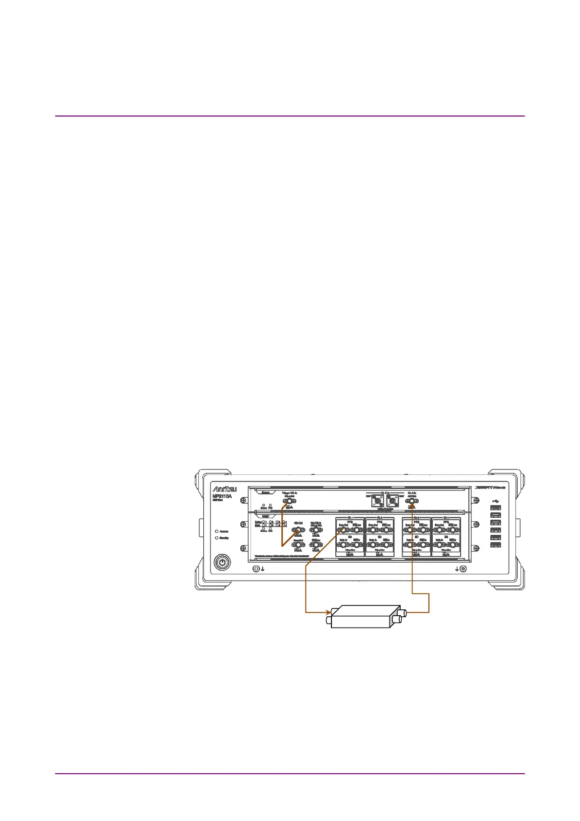
5.2.6 Setting Clk Out
Set a signal output from the
Clk Out
connector on the front panel.
Clk Out is a function to output the clock synchronized to the data
generated from the pulse pattern generator to the
Clk Out
connector on
the front panel. The
Clk Out
connector is AC-coupled.
To measure the eye waveform using the sampling oscilloscope, connect the
Clk Out
connector and the
Trigger Clk In
connector of the sampling
oscilloscope using a coaxial cable.
For MP2110A-093, the clock output division rate is automatically changed
according to the bit rate.
24.3 to 28.2 Gbit/s: 1/4Clock
9.5 to 14.2 Gbit/s: 1/2Clock
For MP2110A-014, the clock source of clock output is selected from Ch1/2
or Ch3/4.
The jitter is reduced by matching the channel used for the measurement
and the channel at Clk Out as shown in Figure 5.2.6-1. Refer to the
descriptions at Jitter in Section A.2.2, “Pulse Pattern Generator”, for
details of the jitter.
To perform the measurement using PPG/ED Ch1 and PPG/ED Ch2, set
Ch1/2.
Figure 5.2.6-1 Connection Example When Setting Ch1/2 at Clk Out
To perform the measurement using PPG/ED Ch3 and PPG/ED Ch4, set
Ch3/4.