5.2 PPG/ED Panel
5-15
5
How to Operate BERT
The Sync Output amplitude cannot be set.
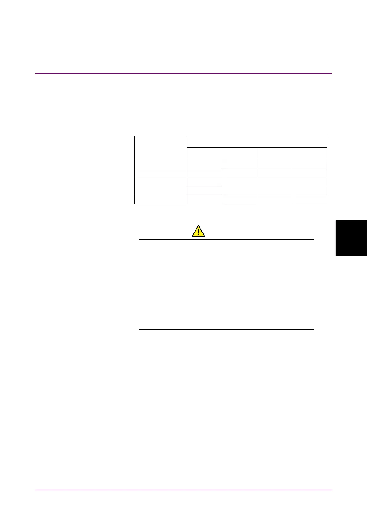
The time interval outputting the pulse varies depending on the pattern
length and bit rate when Sync Output is Pattern Sync .
Select the pattern for the measurement referring to Table 5.2.5-1.
Table 5.2.5-1 Cycle of Sync Output (Pattern Sync)
Pattern Name
Bit Rate (kbit/s)
10 000 000 14 025 000 25 781 250 28 050 000
PRBS 2^7–1 12.7 ns 9.1 ns 4.9 ns 4.5 ns
PRBS 2^9–1 51.1 ns 36.4 ns 19.8 ns 18.2 ns
PRBS 2^15–1 3.28
s 2.34
s 1.27
s 1.17
s
PRBS 2^23–1 838.9
s 598.1
s 325.4
s 299.1
s
PRBS 2^31–1 214.7 ms 153.1 ms 83.3 ms 76.6 ms
CAUTION
The impedance of the Sync Out connector is 50 Ω.
Measurement may not be performed correctly if a
coaxial cable with another impedance is used or if the
impedance of the DUT is not 50 Ω.
The output voltage of the Sync Out connector is –1.2 to
0 V. Check that the output voltage does not exceed the
DUT maximum input specifications. If it does, connect
an attenuator to the Sync Out connector.
Note:
PPG Pattern Sync cannot be set for the following Scope setting.
Time dialog box
Data Clock Rate: Tracking On
Procedure
1. Click Sync Out.
2. Select the type of signal output to Sync Output.