Chapter 5 How to Operate BERT
5-18
5.2.8 Setting Error Detection Method
Set the conditions for detecting a bit error.
Signal input connectors
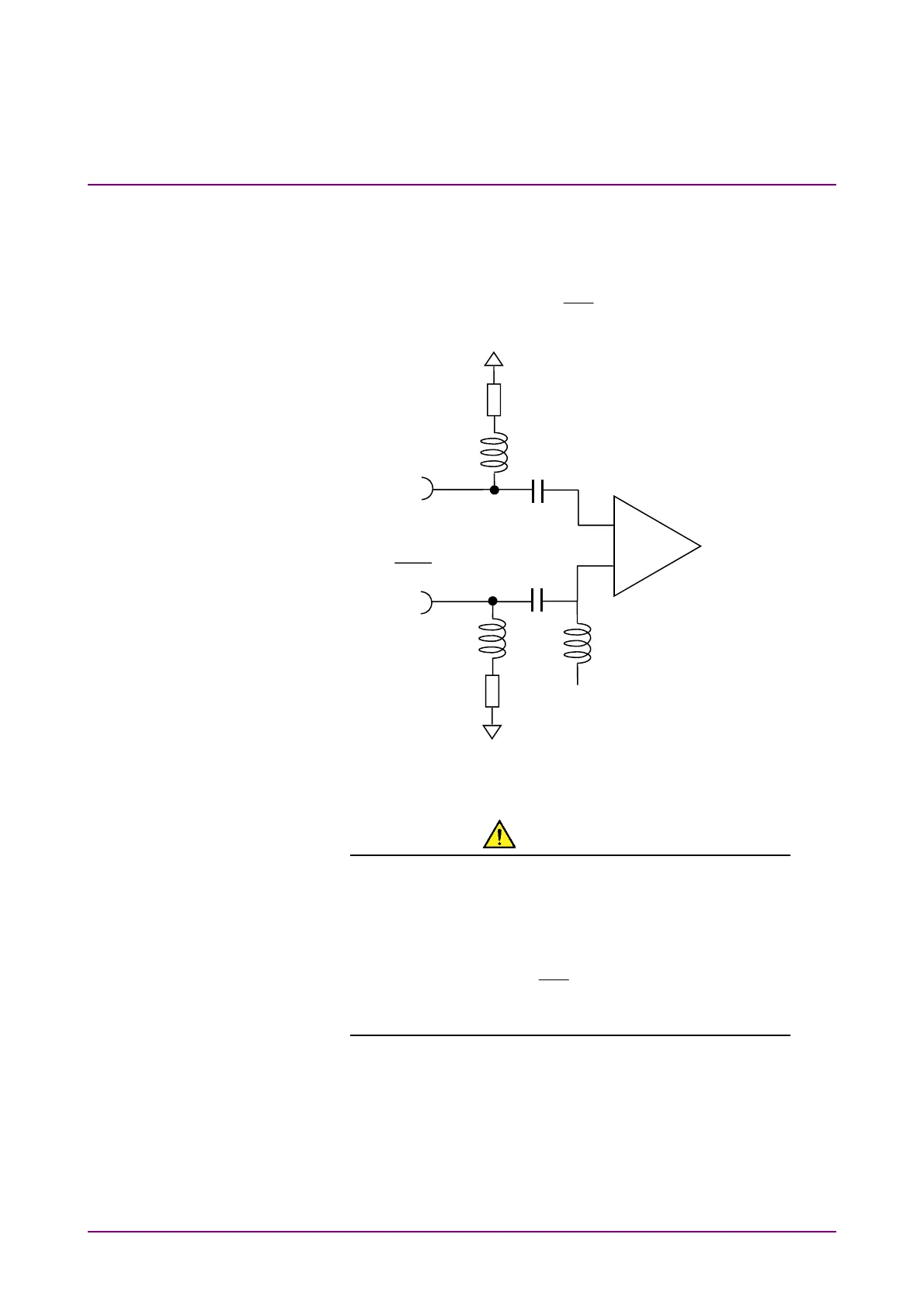
The block diagram for
Data In
and
Data
In
connectors on BERT panel is
as shown below.
Figure 5.2.8-1 Input Connector Block Diagram
CAUTION
●
The impedance of the electrical input connector is 50 Ω.
Measurement may not be performed correctly if a
coaxial cable with another impedance is used.
●
Do not apply a DC voltage of more than 1 V to the Data
In connector and the
Data
In connector. Otherwise, the
internal circuits may be damaged.
Data In
Threshold voltage
+
–
Data In