Chapter 3 Measurement Examples
3-4
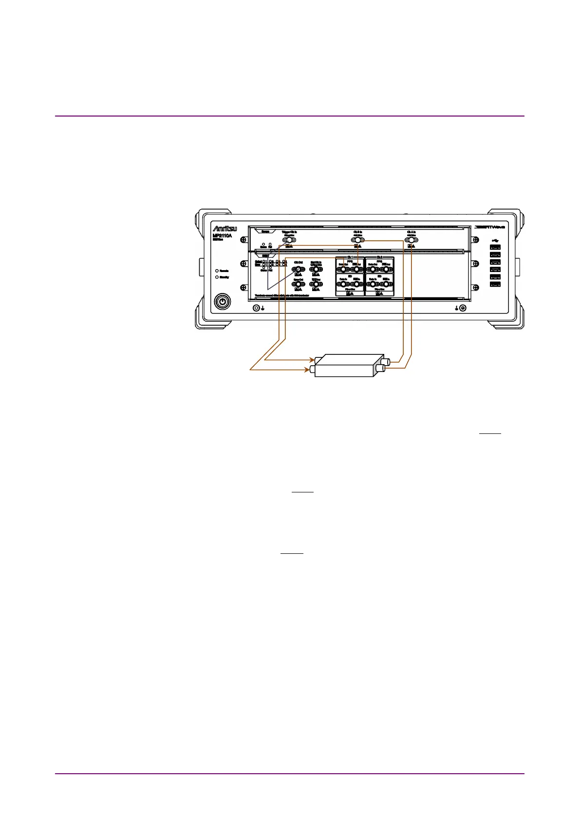
3.2 Measuring Waveform
When measuring the DUT with electrical signal inputs and outputs:
Input the output signal of the built-in PPG to the DUT, and then measure
the DUT output using the sampling oscilloscope.
Figure 3.2-1 When Measuring DUT With Electrical Signal Inputs and
Outputs (MP2110A-012, 021)
1. Connect the DUT input connectors to PPG1
Data
Out
and
Out
using coaxial cables.
If the DUT has only one input connector, connect it to the PPG1
Data
Out
. Also, connect the coaxial terminator included as a standard
accessory to the
Out
.
2. Connect the
Clk Out
(or
Sync Out
) on BERT to
Trigger Clk In
on
Scope using a coaxial cable.
When the
Sync Out
is connected, connect the supplied coaxial
terminator to
Out
.
3. Connect the DUT output connectors to
Ch A In
and
Ch B In
on the
sampling oscilloscope using coaxial cables.
When the amplitude of the input signal is greater than 400 mVp-p,
connect the attenuators to
Ch A In
and
Ch B In
for more accurate
measurement.
 Loading...


