Chapter 5 How to Operate BERT
5-14
5.2.5 Setting Sync Out
Set the signal type output from the front-panel
Sync Out
connector.
Sync Out
connector outputs a clock synchronized to the data generated by
the PPG. The
Sync Out
Connector is a DC coupling.
To monitor the waveform pattern of the pulse pattern generator, set
Pattern Sync at Sync Out and connect the
Sync Out
connector and the
Trigger Clk In
connector of the sampling oscilloscope using a coaxial cable.
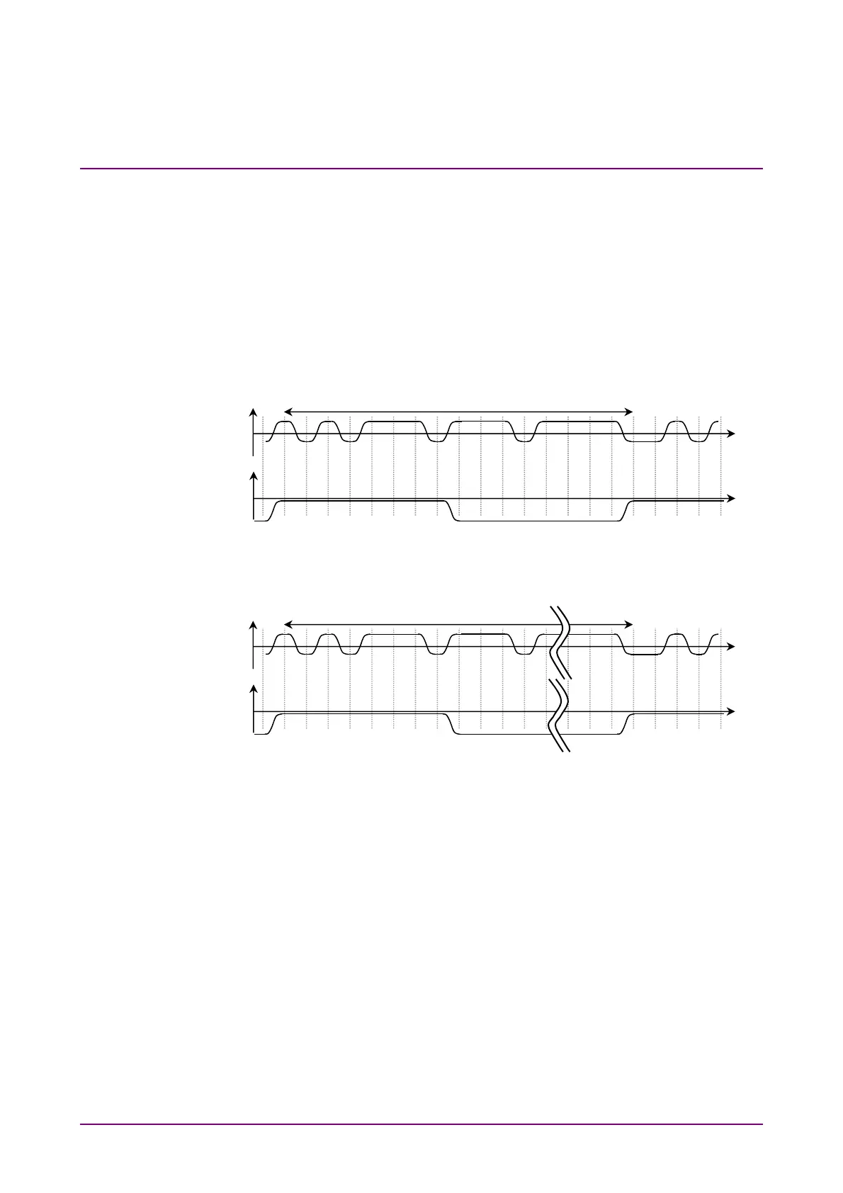
Figure 5.2.5-1 Correspondence between Sync Output Setting and Output Voltage
Waveform at Connector using PPG Rate Division
Figure 5.2.5-2 Voltage Waveform Output to Connector Corresponding to Sync Output
Setting for Pattern Sync
Data Connecto
Voltage
Time
Time
0
0
Sync Out Connecto
Voltage
8, 16, or 40
Data Connecto
Voltage
Time
Time
0
0
Sync Out Connecto
Voltage
Pattern Length