7.1 Performance Test for Pulse Pattern Generator
7-9
7
Performance Test
7.1.4 Skew
(1) Specification
±8 ps (Amplitude 0.3 Vp-p, 25.78125 Gbit/s)
(2) Setup
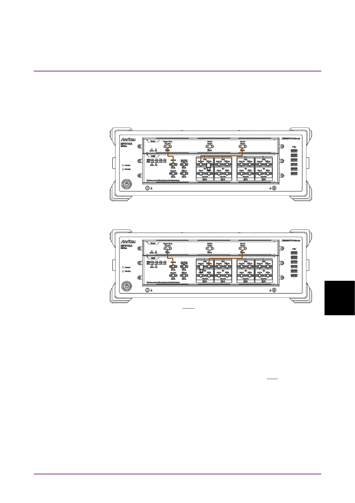
Figure 7.1.4-1 PPG1 Data Out Skew Test Connection Diagram
Figure 7.1.4-2 PPG1
Data
Out Skew Test Connection Diagram
(3) Procedure
1. Connect the
Clk Out
connector and the
Trigger Clk In
connector
of the sampling oscilloscope using a coaxial cable.
2. Connect the
PPG1 Data Out
connector and the
Ch A In
connector
of the sampling oscilloscope using a coaxial cable.
3. Connect the coaxial terminator to the
PPG1
Data
Out
connector.
(refer to Figure 7.1.4-1).