Chapter 7 Performance Test
7-8
10. Click PPG/ED Ch1.
11. Set Amplitude to 0.3 Vp-p.
12. Click Scope. Configure the settings as shown below:
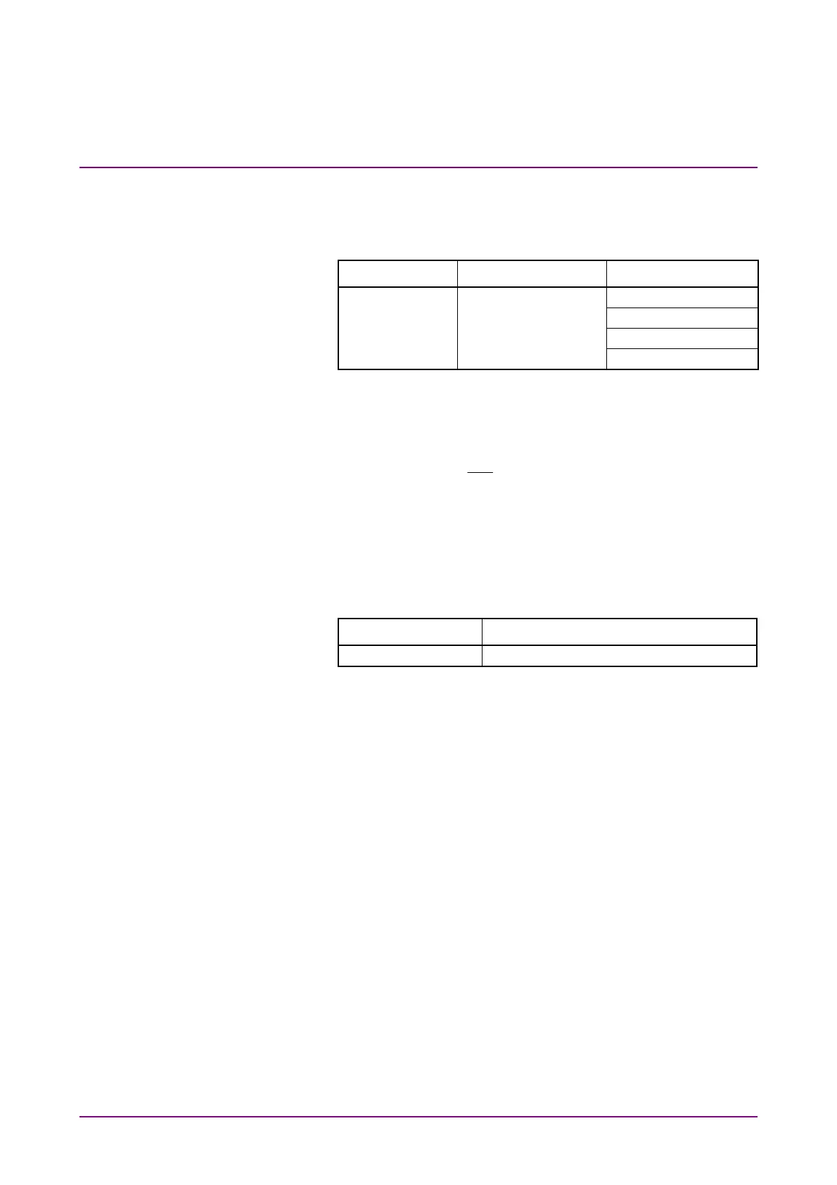
Dialog Box Item Setting Value
Measure - Item (A) Fall Time
Amplitude/Time (A) Rise Time
(A) Crossing
(A) Jitter RMS
13. Measure the amplitude, rise/fall time, and Data Crossing on the
sampling oscilloscope.
14. Connect the coaxial terminator to the
PPG1 Data Out
connector.
(Refer to Figure 7.1.3-4.)
15. Connect the
PPG1
Data
Out
connector to the
Ch A In
connector
of the sampling oscilloscope.
16. Repeat steps 4 to 13.
For PPG2 to PPG4, perform tests in the same way. For PPG3 and PPG4
test, change the Clock Output in step 4 to the following value.
Item Setting Value
Clock Output Ch3/4