7.1 Performance Test for Pulse Pattern Generator
7-7
7
Performance Test
(3) Procedure
1. Connect the coaxial terminator to the
PPG1
Data
Out
connector.
2. Connect the
Clk Out
connector and the
Trigger Clk In
connector
of the sampling oscilloscope using a coaxial cable.
3. Connect the
PPG1 Data Out
connector and the
Ch A In
connector
of the sampling oscilloscope using a coaxial cable.
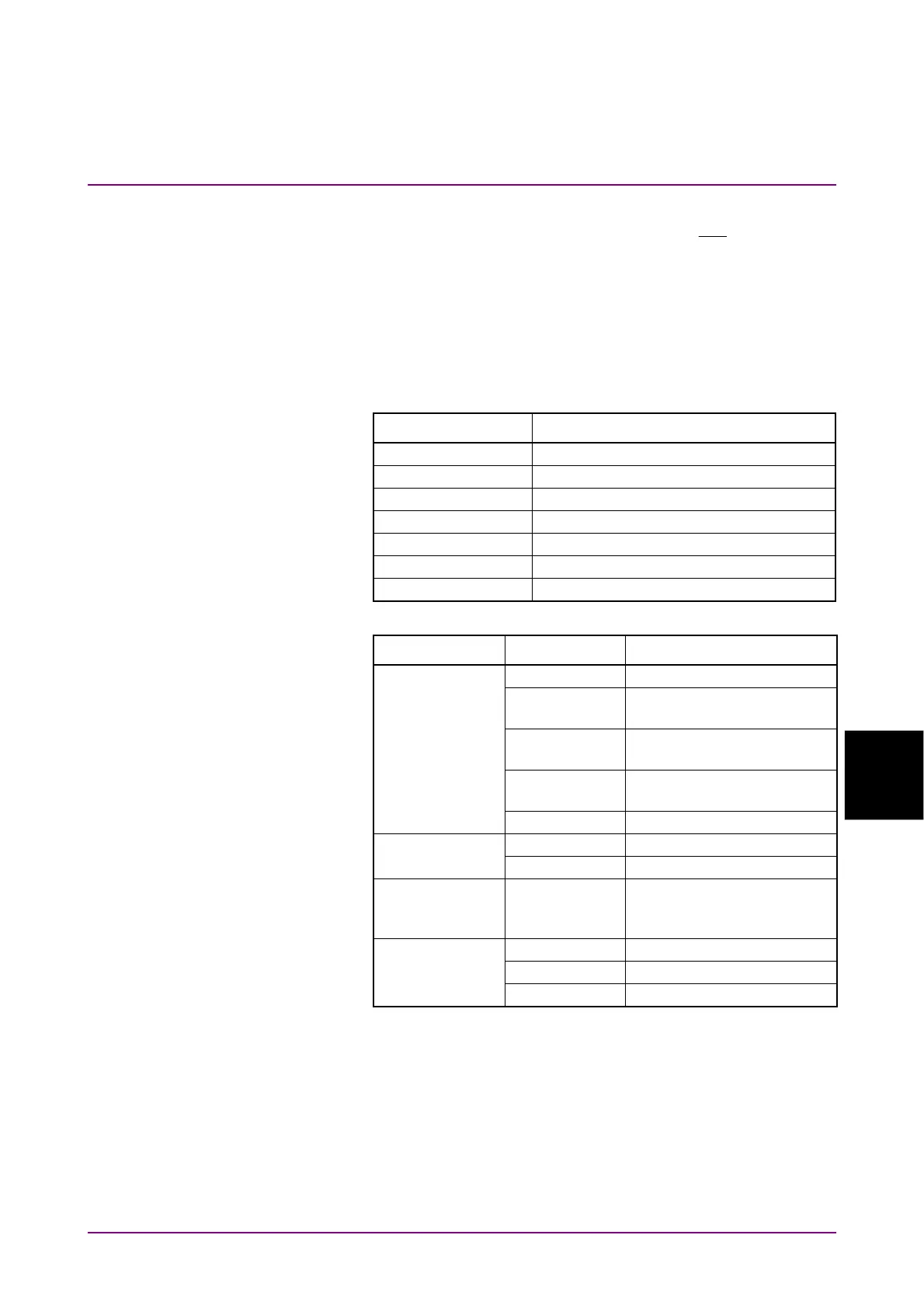
4. Click PPG/ED Ch1. Configure the settings as shown below:
Item Setting Value
Reference Clock Internal
Bit Rate 100GbE/4 (25.78125G), 0 ppm
Clock Output Ch1/2
PPG Amplitude 0.1
External ATT 0
Test Pattern (PPG) PRBS 2^31–1, POS
PPG Data/XData ON
5. Click Scope. Configure the settings as shown below:
Dialog Box Item Setting Value
Setup Signal Type NRZ
Sampling
Mode
Eye
Number of
Samples
4050
Accumulation
Time
Persistency
Time 10.0 sec
Amplitude Scale 100 mV/Div
Offset 0 mV
Time Tracking Symbol Rate: PPG,
Divide Ratio: Clock
Output*
Measure - Display On
Amplitude/Time Item (A) Eye Amplitude
Rise/Fall Time 20/80%
*: Set it to Off when using two MP2110As (Figure 7.1.3-3 and
Figure 7.1.3-4), and input Divide Ratio.
6. Click Ch A, Sampling Hold, and Auto Scale of Scope, and
measure the eye amplitude.
7. Click PPG/ED Ch1.
8. Set Amplitude to 0.8 Vp-p.
9. Click Scope. Measure the EYE amplitude on the sampling
oscilloscope.