6.4 Setting CRU
6-63
6
How to Operate Sampling Scope
Setting CRU
6.4
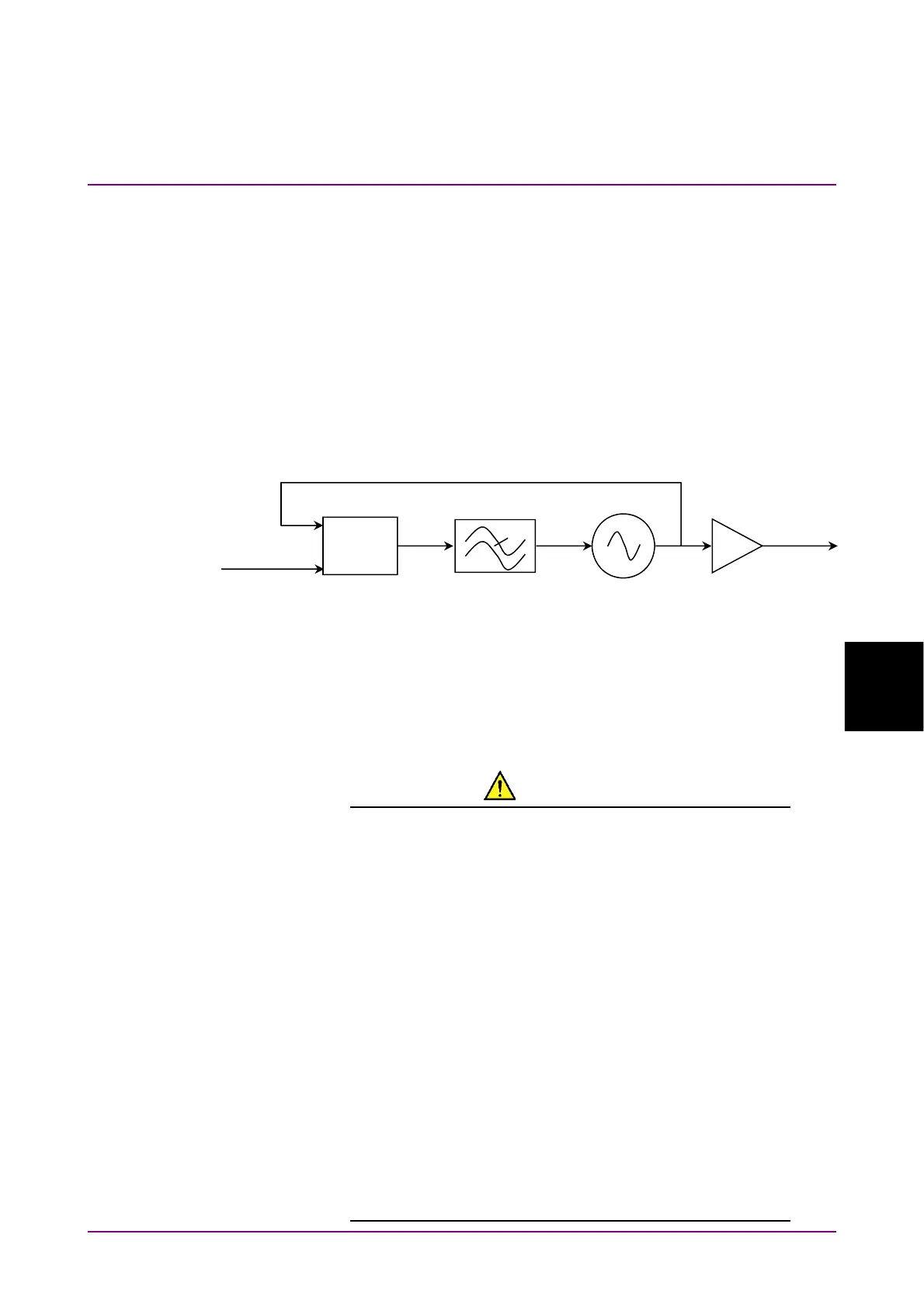
The clock recovery unit (CRU) generates a clock signal from the signal
input to
CRU In
connector.
The waveform can be observed by using the generated clock signal.
The clock recovery unit sets the following.
Operation Rate
CRU Loop BW
Operation Rate sets frequency range.
CRU Loop BW is a loop filter bandwidth that is used in the frequency
control circuit of the clock recovery unit.
Figure 6.4-1 Block Diagram of Clock Recovery Unit
A wider frequency bandwidth can absorb more frequency fluctuations
that occur momentarily. The loop filter bands for the Jitter measurement
are defined in the communication standards.
CAUTION
● The impedance of the CRU In and CRU Out connectors
is 50 Ω. If you use a coaxial cable with impedance other
than 50, or connect a device with impedance other
than 50, the measurement may not be performed
properly.
● The CRU Out connector output voltage is 0.4 to 0.8 Vp-p.
Make sure that the voltage output to the connectors
does not exceed the input voltage range of a device to
be connected. The voltage amplitude to be output to the
CRU Out connector exceeds the input voltage range of
a device to be connected, install an attenuator to the
CRU Out connector.
●
The amplitude of the signal input to the CRU In
connector is 0.8 Vp-p max. This is equivalent to +2 dBm
for a sine-wave signal. Inputting a signal with a larger
voltage risks damaging the internal circuits.
Phase
Com
arator
Input Signal
Loop Filter
Voltage-Controlled
Oscillator
Buffer Amplifier
CRU Ou
CRU In