Chapter 6 How to Operate Sampling Scope
6-64
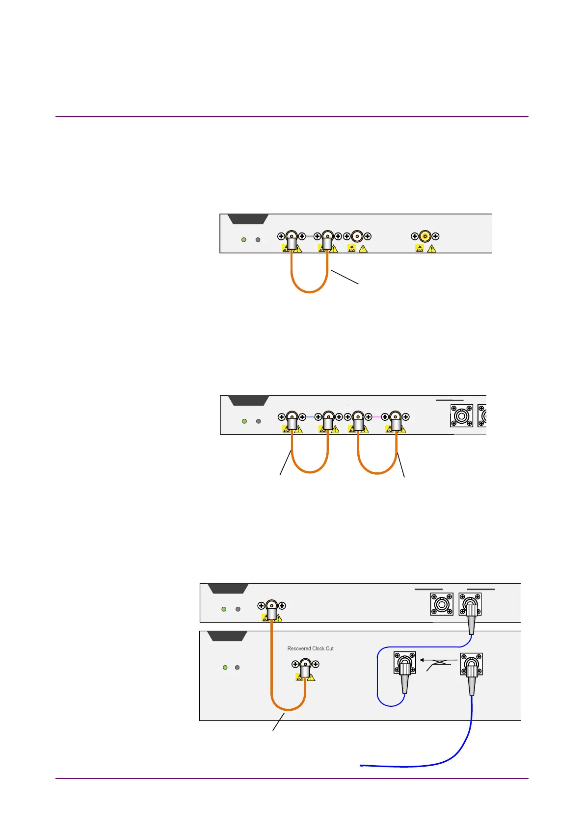
Procedure
1. For MP2110A-054
Connect the
CRU Out
and
Trigger Clk In
connectors with a
supplied U-link coaxial cable (SMA).
If the Scope module is equipped with
O/E Monitor Out
connector,
Clock Recovery can be executed from Channel B optical signal
input by connecting the
O/E Monitor Out
and
CRU In
connectors
with a U-link coaxial cable (K). If the
O/E Monitor Out
and
CRU
In
connectors are not connected, make sure to install a coaxial
terminator to the
O/E Monitor Out
connector.
For MP2110A-055
Connect the
Data Out
connector of 53G CRU and the
SMF In
connector of the scope, using a single-mode optical fiber. Connect
the
Recovered Clock Out
connector of 53G CRU and the
Trigger
Clk In
connector of the scope, using a coaxial cable (SMA).
Trigger Clk In
2Vp-p Max
Ch B In
±2V Max
Sco
e
Status Fail
CRU In
1Vp-p Max
CRU Out
U Link Coaxial Cable (SMA)
Trigger Clk In
2Vp-p Max
Ch B In
Sco
e
Status Fail
MMF
+5dBm Peak Max
CRU In
1Vp-p Max
CRU Out
O/E Monitor Out
U Link Coaxial Cable (K)
U Link Coaxial Cable (SMA)
Trigger Clk In
2Vp-p Max
Sco
e
Status Fail
U Link Coaxial Cable (SMA)
CRU
Status Fail
Data Out
Data In
Optical
SMF
Ch B In
MMF
SMF
+5dBm Peak Max
To input the measured signal