6.4 Setting CRU
6-65
6
How to Operate Sampling Scope
2. For MP2110A-054
Input the signal to the
CRU In
connector.
For MP2110A-055
Input the signal to the
Data In
connector.
3. Click Time CRU.
4. Click the CRU tab. When both MP2110A-054 and MP2110A-055 are
installed, click the CRU(26G) or CRU(53G) tab.
5. Click the Operation Mode button and set the display to Recovery.
When locked on the signal input to the
CRU In
or
Data In
connector,
the Lock Status indicator turns green.
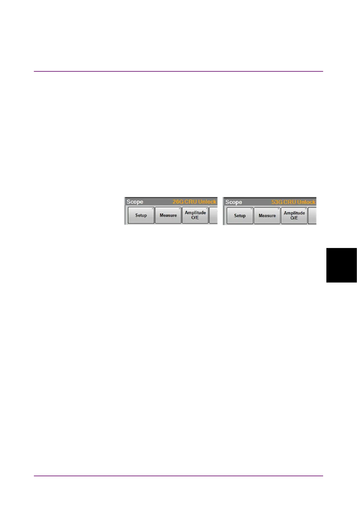
If the Lock Status indicator is not on, “CRU Unlock” is displayed in
the Result window.
6. Click the Operation Rate button and set the symbol rate.
7. Click the CRU Loop BW button and select the loop bandwidth from
the following:
4 MHz, 10 MHz, Bitrate/1667
8. Click Rate tab.
9. Click the Tracking button and set the display to CRU.
Notes:
● When the clock recovery unit is not used, set Operation Mode to
OFF on the CRU tab.
● If the frequency of the input signal to the clock recovery unit is
outside the frequency band set for Operation Rate, the clock
recovery unit may not recover the clock. At that time, “CRU
Unlocked” is displayed in the Result window.
● When the clock recovery unit is used, the symbol rate displayed
at the bottom right in the waveform area may not be a desired
value. At that time, check the signal waveform, frequency, and
amplitude to input to the clock recovery unit. When the Lock
Status indicator turns green and the CRU is locked on the input
signal, click Acquire Clock Rate on the Rate tab.
MP2110A-054
MP2110A-055