Appendix A Specifications
A-14
A.3.3 Time Setting
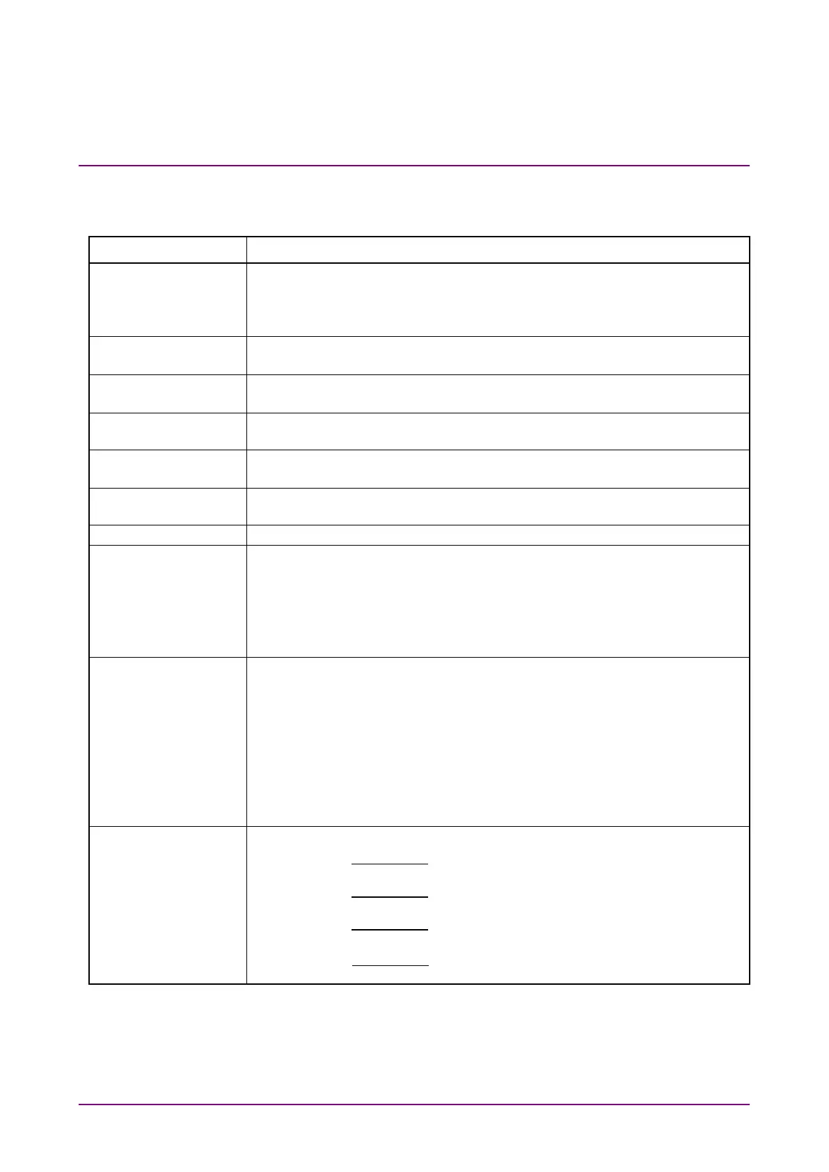
Table A.3.3-1 Time Setting
Item Specifications
Specifies the reference parameter
Symbol Rate (Symbol Rate is automatically set when Clock Rate is
entered)
Clock Rate (Clock Rate is automatically set when Symbol Rate is entered)
Specifies the baud rate of the signal input to the Scope channel
100 Mbaud to 60 Gbaud, 1 kbaud step
Specifies the clock frequency input to Trigger In
100 MHz to 15 GHz, 1 kHz step
Function that sets Symbol Rate and Divide Ratio to values set by other
options, when BERT or Clock Recovery option is installed
Uptates Clock Rate by measuring the clock rate input to Trigger In
(Data Rate is automatically set according to the Divide Ratio)
Ratio of Clock and Input Data (1 to 99. However, Pulse / Coherent Eye Mode
works only when setting 1, 2, 4, 8, 16, 32, 40, 48, 64)*
1
Detects Divide Ratio automatically
ON/OFF (Trigger Clock ON is possible at input frequency of 2.4 GHz or
higher)
Ability to redetect the internal correction value for Precision Trigger
Ability to display status to the user when the internal correction value
becomes inappropriate
Specifies the horizontal axis unit of the screen
UI, Time(ps)
Specifies the number of UI on the screen
Eye, Coherent Eye Mode: 1 to 100 UI (1 UI step)
Pulse Mode: 1 to 65535 UI (1 UI step)
Sets time offset for trigger position
0.00 to 32768.00 UI (0.01 UI step)
Available only when Sampling Mode is Pulse.
Function of correcting Inter-channel phase delay
Channel A: Display UI converted to ps (0.1 ps step)
Channel B: Display UI converted to ps (0.1 ps step)
Channel C: Display UI converted to ps (0.1 ps step)
Channel D: Display UI converted to ps (0.1 ps step)
*1: 48 is supported by Version 6 or later.
*2: Available when MP2110A-024 is installed





 To Next Page