Chapter 7 Performance Test
7-10
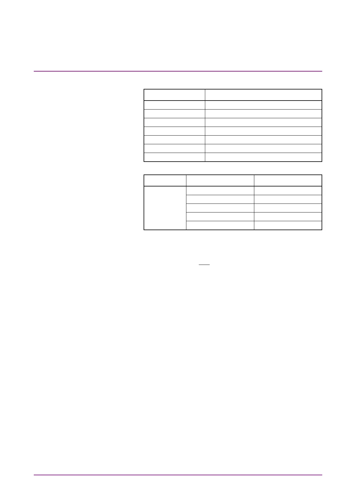
4. Click PPG/ED Ch1. Configure the settings as shown below:
Item Setting Value
Reference Clock Internal
Bit Rate 100GbE/4 (25.78125G), 0 ppm
Clock Output Ch1/2
PPG Amplitude 0.3 Vp-p
External ATT 0 dB
Test Pattern (PPG) PRBS 2^9–1, POS
PPG Data/XData ON
5. Click Scope. Configure the settings as shown below:
Dialog Box Item Setting Value
Setup Signal Type NRZ
Sampling Mode Eye
Number of Samples 4050
Accumulation Time Persistency
Time 10.0 sec
6. Display the X1 marker by clicking Marker of Scope, and move
the X1 marker to the left cross-point.
7. Connect the coaxial terminator to the
PPG1 Data Out
connector.
8. Connect the
PPG1
Data
Out
connector to the
Ch A In
connector
of the sampling oscilloscope. (refer to Figure 7.1.4-2).
9. Display the X2 marker by clicking Marker of Scope, and move
the X2 marker to the left cross-point.
10. When the time unit is UI, change Unit in the Scale/Offset tab to
Time by clicking Time of Scope.
11. Measure the time lag of two waveforms using the X1 and X2
markers. Note that the polarities of two waveforms are inverted.