3.2 Measuring Waveform
3-7
3
When the DUT is an optical transceiver:
When the MP2110A-022, 023, 025, 026, 030, 032, 033, 035, 036, 039, 040,
042, 043, 045, 046 or 049 is selected, the output waveform of the optical
transceiver can be measured using the O/E.
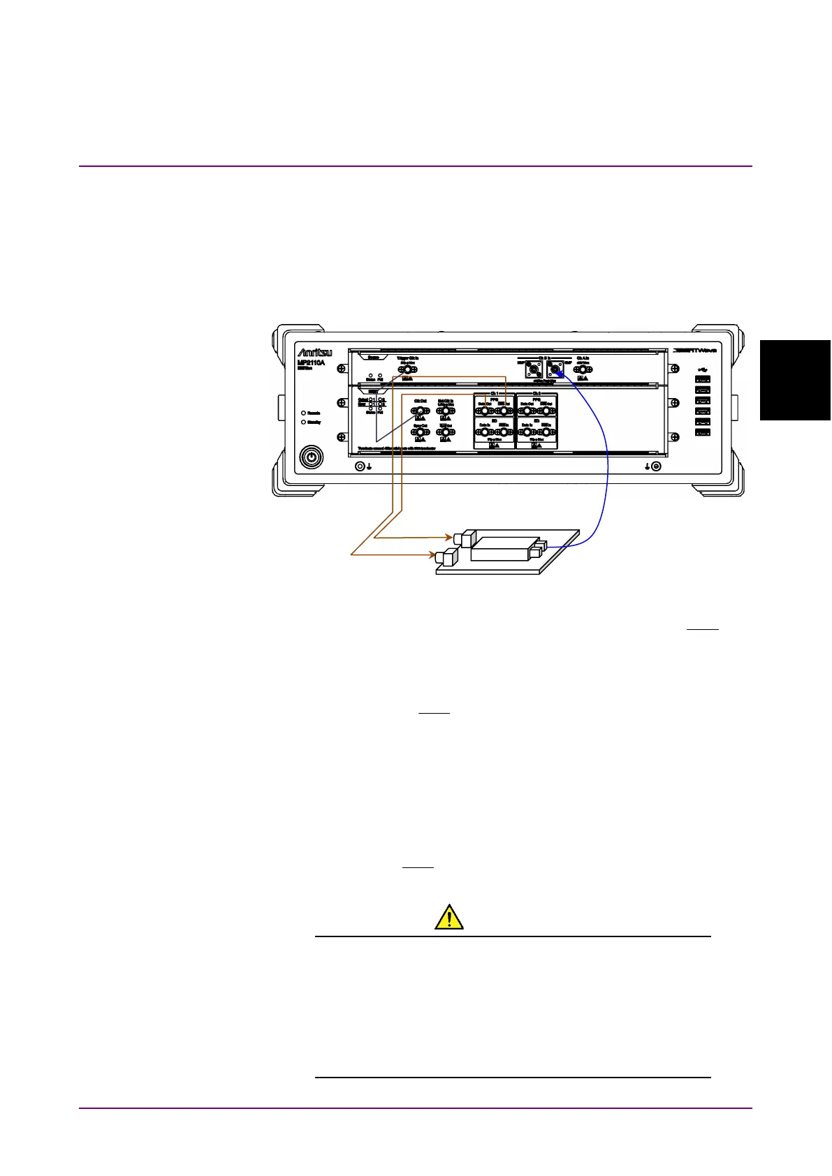
Input the output signal of the built-in PPG to the DUT, and then connect
the DUT optical output to the SMF or MMF.
Figure 3.2-4 When DUT is Optical Transceiver (MP2110A-012, 023)
1. Connect the DUT input connectors to PPG1
Data Out
and
Out
using coaxial cables.
If the DUT has only one input connector, connect it to the PPG1
Data
Out
. Also, connect the coaxial terminator included as a standard
accessory to the
Out
.
2. Connect the DUT optical output connector to
Ch B In
using an optical
fiber. When the DUT wavelength is 850 nm, connect it to
MMF
. When
the DUT wavelength is 1310 nm or 1550 nm, connect it to
SMF
.
3. Connect the
Clk Out
(or
Sync Out
) to
Trigger Clk Input
using a
coaxial cable.
When the
Sync Out
is connected, connect the supplied coaxial
terminator to
Out
.
CAUTION
Check that the DUT optical output level does not exceed
the rated optical input level for Ch B In.
There is a risk of damaging the built-in O/E module if the
optical power exceeding the rated optical input level is
applied to the Ch B In connector.
 Loading...


