Chapter 5 How to Operate BERT
5-12
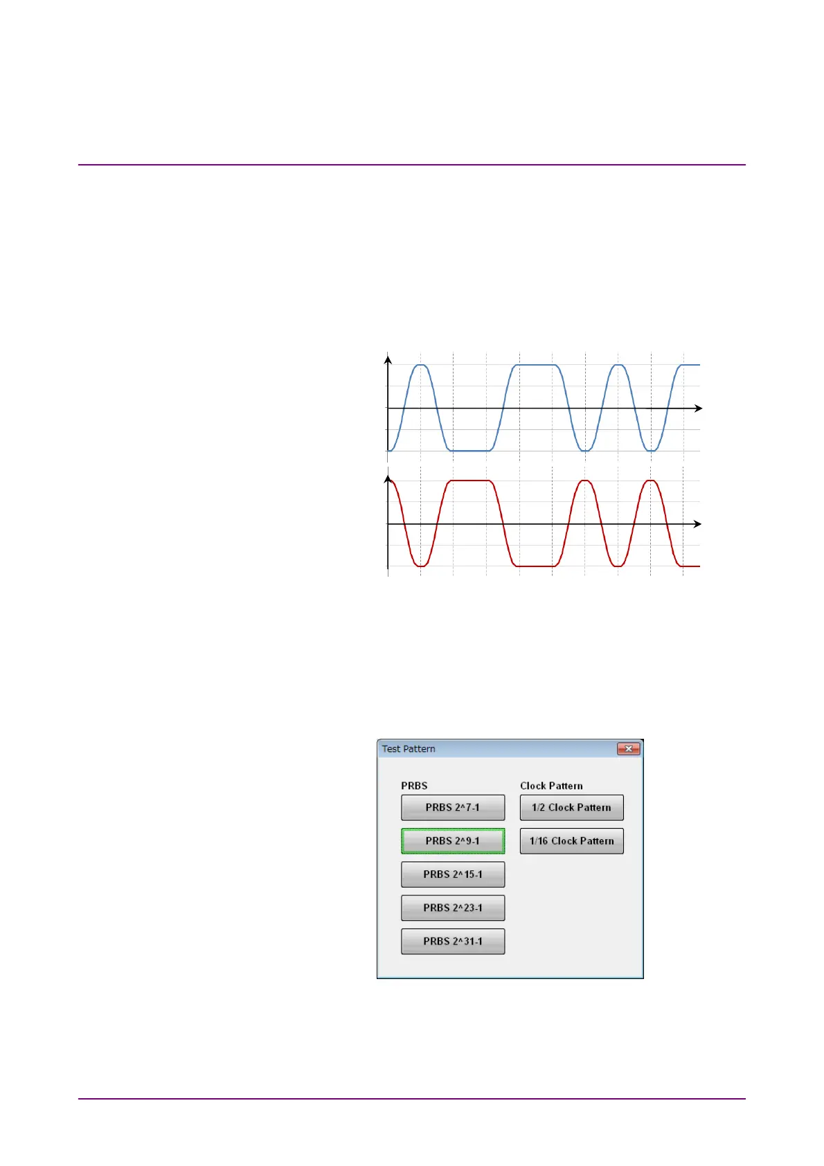
Pattern Logic
There are two types of logic; Positive Logic (POS) and Negative Logic
(NEG).
With positive logic, the voltage at the Data connector goes High when the
data is “1”.
With negative logic, the voltage at the Data connector goes Low when the
data is “1”.
Figure 5.2.3-4 Relationship between Logic Setting and Output Voltage
Waveform at Connector
Set the pattern using the following procedure.
1. Click the button for Test Pattern, and you will see the Test Pattern
dialog box.
2. Click the button for the pattern you want to set.
Data connector
voltage if POS
is set
Data connector
voltage if NEG
is set
Time
Time
0
0
Pattern data 0 1 0 0 1 1 0 1 0 1
 Loading...


