Chapter 6 How to Operate Sampling Scope
6-50
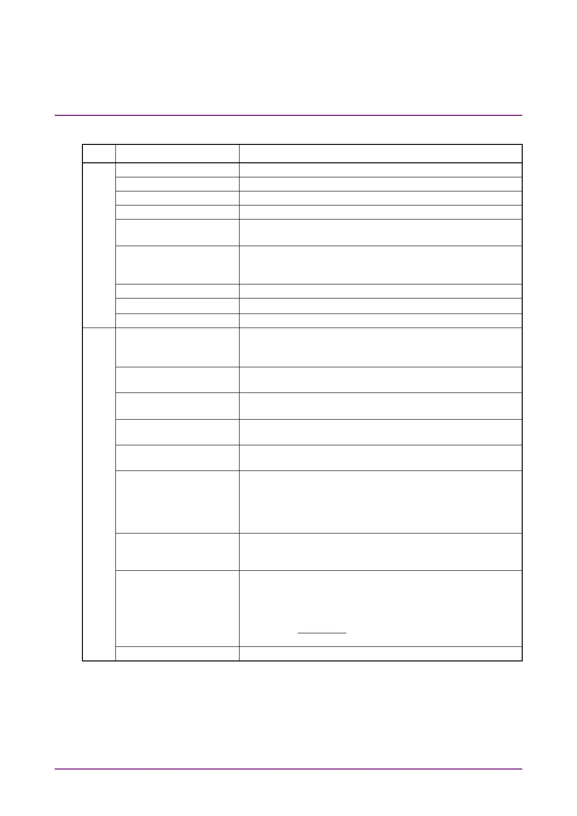
Table 6.2.5-1 Items of Amplitude Dialog Box
Tab Item Description
Scale Offset
Scale Offset Sets the level scale.
Scale Sets vertical scale.
Offset Sets vertical offset.
Attenuation Sets attenuation amount for external attenuation.
Tracking Off: Sets the scale for the active channel.
On: Sets the scale for all channels to the same value.
Channel Math*
1
Off: Displays waveforms for Channel A and B separately.
On: Calculates waveforms for Channel A and B, and then
that calculated result is displayed as Channel A.
Define Function*
1
Sets calculation method between channels.
Scale Sets vertical scale for calculation result between channels.
Offset Sets vertical offset for calculation result between channels.
O/E
Input Connector
(Wavelength)*
1,
*
2
Select the wavelength of input light from the following:
MMF connector: 850 nm, User
SMF connector: 1310 nm, 1550 nm, User
Conversion Gain*
2
Indicates the conversion ratio of the O/E.
The setting range is from 1 to 9999 (V/W).
Responsivity*
2
Rate at which photodiode converts optical power to current
The setting range is from 0.001 to 65.535.
Calibration*
2
Automatically adjusts the values of Conversion Gain and
Responsivity when Wavelength is User.
Input Power*
2
Setting used when performing calibration of Conversion Gain
and Responsivity.
Filter Selection*
1
When MP2110A-095 is installed, the filters for 400GbE and
64GFC are added. Since these filters use digital signal
processing, they can be used under the following conditions.
Sampling Mode is set to Coherent Eye
Test Pattern is set to other than Variable
Extinction Ratio
Correction
Sets whether to correct the Extinction Ratio measurement.
This correction is applied to the results of Extinction Ratio
and Outer ExR
Correction Factor Indicates the correction factor of Extinction Ratio.
The setting range is from –9.99 to 9.99%.
Extinction Ratio is corrected using the following formula:
Extinction Ratio (dB) =
–10log
Zero Level
One Level
– Correction Factor
O/E Calibration Starts module calibration.
*1: When Sampling Mode is set to Advanced Jitter, it can be operated
while stopping measurement.
*2: When 850 nm, 1310 nm, or 1550 nm is selected at Wavelength, the
values calibrated before factory shipment are set at Conversion Gain
and Responsivity.