6.2 Explanation of Windows
6-55
6
How to Operate Sampling Scope
● When Reference Clock of PPG is set to External, Tracking is set to
other than Off.
● When Clock Out of PPG is set to Off, Tracking is set to Clock Out.
*2: When MP2110A-054 or MP2110A-055 is installed
*3: When MP2110A-054 and MP2110A-055 are installed
*4: When MP2110A-024 is installed
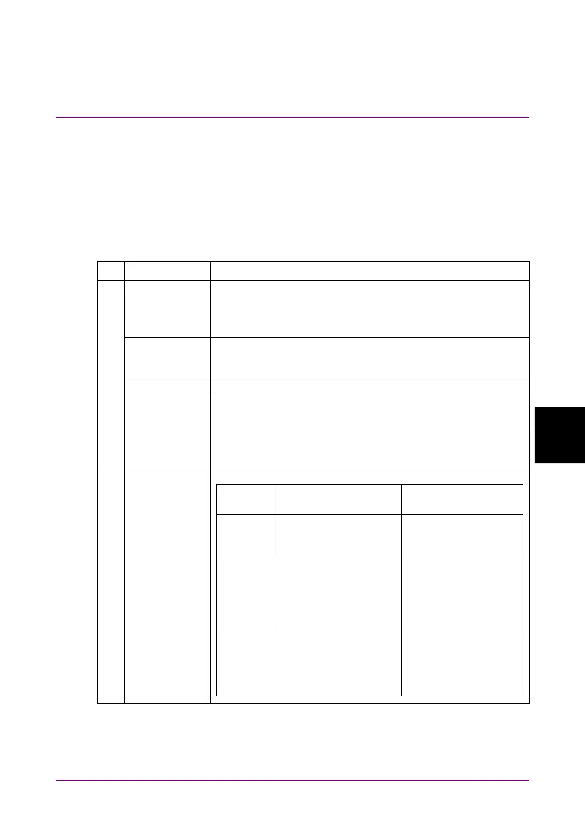
Table 6.2.6-1 Items of Time Dialog Box (Cont’d)
Tab Item Description
Scale/Offset
Unit Sets units of horizontal axis on Waveform display area.
UI On Screen Sets the scale on the horizontal axis of the Waveform display area as
the number of unit intervals.
Offset*
5
Sets time on left side of Waveform display area.
Pattern Length Sets input data pattern length.
Tracking Off: Allows you to directly set the pattern length in the Length box.
On: Sets pattern length selected at Master to Length.
Master Selects the item that reflects the pattern length.
Length Sets the pattern symbol length.
If the Test Pattern of the General tab in the Setup dialog box is
Variable, specify the symbol length.
Software Delay Sets time offset.
Setting positive values moves the waveform to the right.
Setting negative values moves the waveform to the left.
CRU, CRU(26G). CRU(53G)
Operation Mode Selects the operation of the clock recovery unit.
*5: This is displayed only when Sampling Mode is Pulse.
Operation
Mode
MP2110A-054 MP2110A-055
OFF Clock is not output from
the
CRU Out
connector.
Clock is not output from
the
Recovered Clock
Out
connector.
Recovery The clock recovered from
the data signal input to
the
CRU In
connector is
output to the
CRU Out
connector.
The clock recovered from
the data signal input to
the
Optical SMF Data In
connector is output to
the
Recovered Clock
Out
connector.
Through The data signal input to
the
CRU In
connector is
output to the
CRU Out
connector as it is.
The data signal input to
the
Optical SMF Data In
connector is output to
the
Recovered Clock
Out
connector as it is.