Chapter 7 Performance Test
7-20
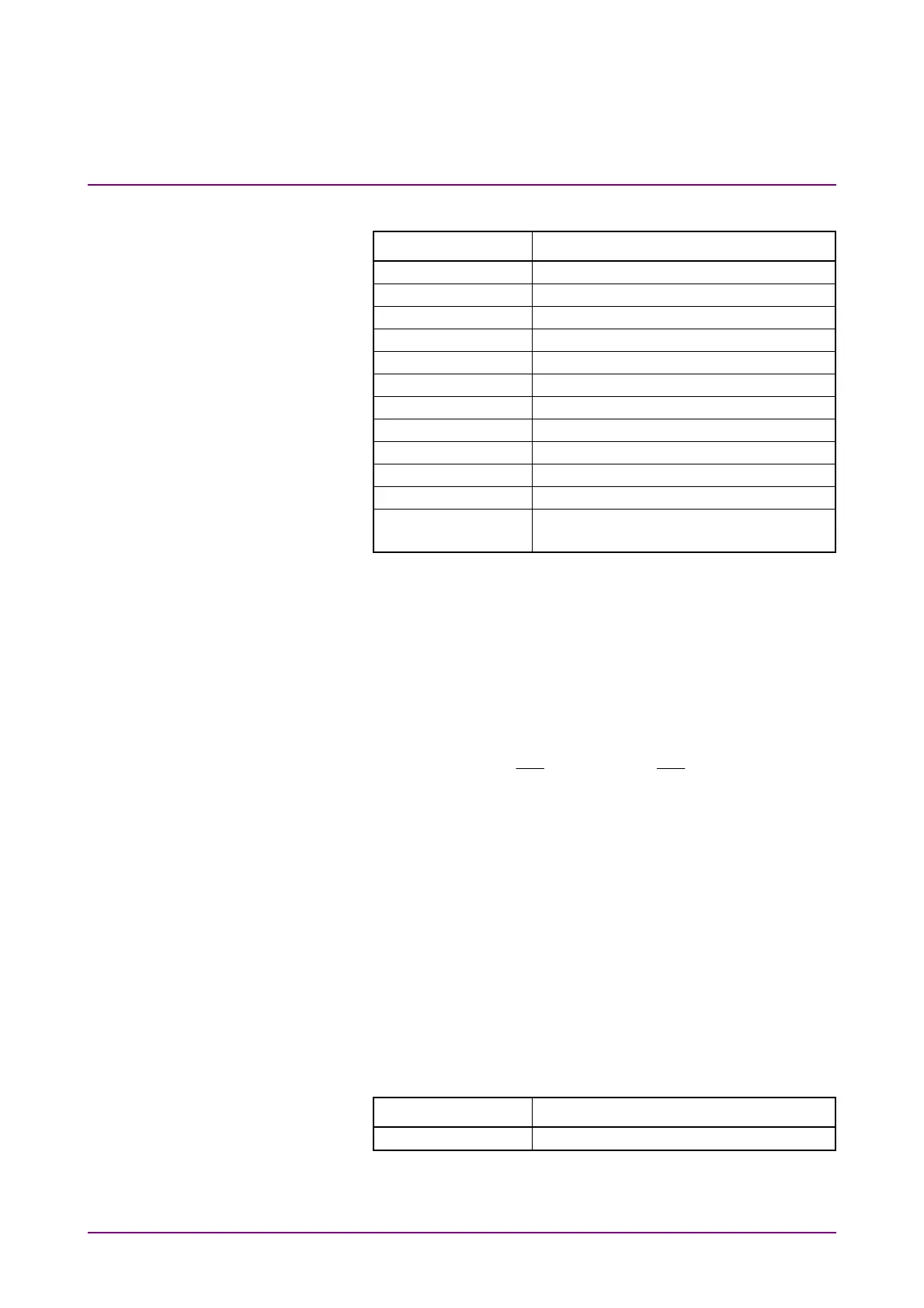
3. Click PPG/ED Ch1. Configure the settings as shown below:
Item Setting Value
Reference Clock Internal
Symbol Rate 100GbE/4 (25.78125G), 0 ppm
Clock Output Ch1/2
PPG Amplitude 0.8
External ATT 0
Test Pattern (PPG) PRBS 2^31–1, POS
Test Pattern (ED) PRBS 2^31–1, POS
ED Input Condition Single-Ended Data
Threshold 0 mV
PPG Data/XData ON
Gating Cycle Single
Gating Period 45 s (28.2 Gbit/s or 24.3 Gbit/s)
120 s (9.5 Gbit/s)
4. Click Start at All Measurements.
5. After measurement, confirm that the error count of the ED
Result is 0.
6. Change Test Pattern for (PPG) and (ED) in succession to PRBS
2^7–1, PRBS 2^9–1, PRBS 2^15–1, and PRBS 2^23–1, and
repeat steps 4 and 5 each time.
7. Connect coaxial terminators to the
PPG1 Data Out
and
ED1
Data In
connectors. (Refer to Figure 7.2.4-2.)
8. Connect the
PPG1
Data
Out
and
ED1
Data
In
connectors using
a coaxial cable.
9. Click PPG/ED Ch1 and set ED Input condition to Single-Ended
XData.
10. Repeat steps 3 to 6.
11. Change the Bitrate to the following value,
When MP2110A-093 is not installed: 24.3 Gbit/s
When MP2110A-093 is installed: 9.5 Gbit/s
12. Repeat steps 1 to 10.
For ED2 to ED4, perform tests in the same way. For ED3 and ED4 test,
change the Clock Output in step 3 to the following value.
Item Setting Value
Clock Output Ch3/4