7.3 Performance Test for Sampling Oscilloscope
7-43
7
Performance Test
(3) Procedure
1. Connect the Sync Clock Out connector of MU100011A and the
Trigger Clk In connector of the scope, using a coaxial cable.
Refer to Figure 7.3.5-1.
2. Connect the output connector of the light source and the input
connector of the programmable optical attenuator, using a
single-mode optical fiber.
3. Connect the output connector of the variable optical attenuator
and the
Ch B In
connector (SMF) of the scope, using a
single-mode optical fiber.
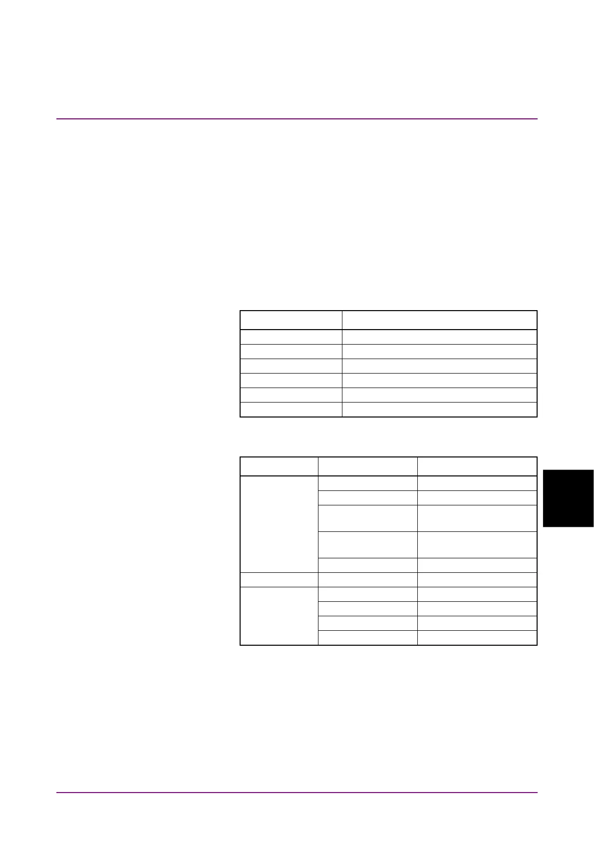
4. Configure the settings for MT1000A. Refer to Figure 7.3.5-2.
Item Setting Value
Application Ethernet BERT
Port SFP28
Sync Port 1/16
Stream Unframed
Payload pattern PRBS31
Cross pattern Selected
5. In the MP2110A window, click Scope. Configure the settings as
shown below:
Dialog Box Item Setting Value
Setup Signal Type NRZ
- General Sampling Mode Eye
Number of
Samples
4050
Accumulation
Time
Persistency
Time 10.0 sec
Time - Rate Tracking Off
Time - CRU* Operation Mode Recovery
Operation Rate 100GbE/4 (25.78125G)
CRU Loop BW 4 MHz
Auto Relock On
*: When both MP2110A-054 and MP2110A-055 are installed,
configure the settings on the CRU(53G) tab.
6. In the Scope screen, click Time, and then on the Rate tab, click
Acquire Clock Rate.
7. Click Ch B of Scope and measure the amplitude.
8. Adjust the attenuation of the variable optical attenuator so that
the eye amplitude of the scope is 244±5 µW.
 Loading...


