1.4 Intended Use
1-19
1
Outline
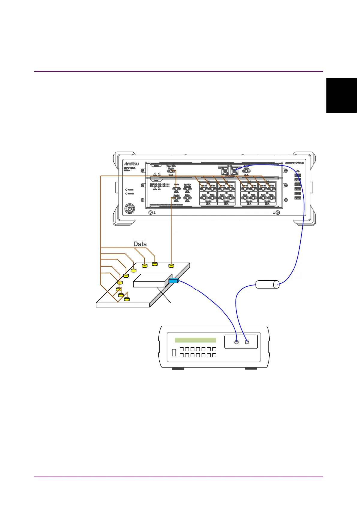
The output waveform of the optical transceiver is evaluated using the
pulse pattern generator and sampling oscilloscope. The output of optical
transceiver is the wavelength multiplexed optic. Therefore, input only the
optic of the wavelength to be measured using the optical demultiplexer or
optical filter to MP2110A.
The following figure shows a connection example between the DUT and
the measuring instruments when the DUT is the CFP4 module.
Figure 1.4-3 Connection Example of Waveform Measurement
Programmable
Optical
Attenuator
Optical Fiber
Optical
Demultiplexer
or Optical Filter
TX1 to TX4
Data and
Reference
Clock
DUT