IDA8 Global-Net User Manual204
© 2020, ATEÏS. All rights reserved.
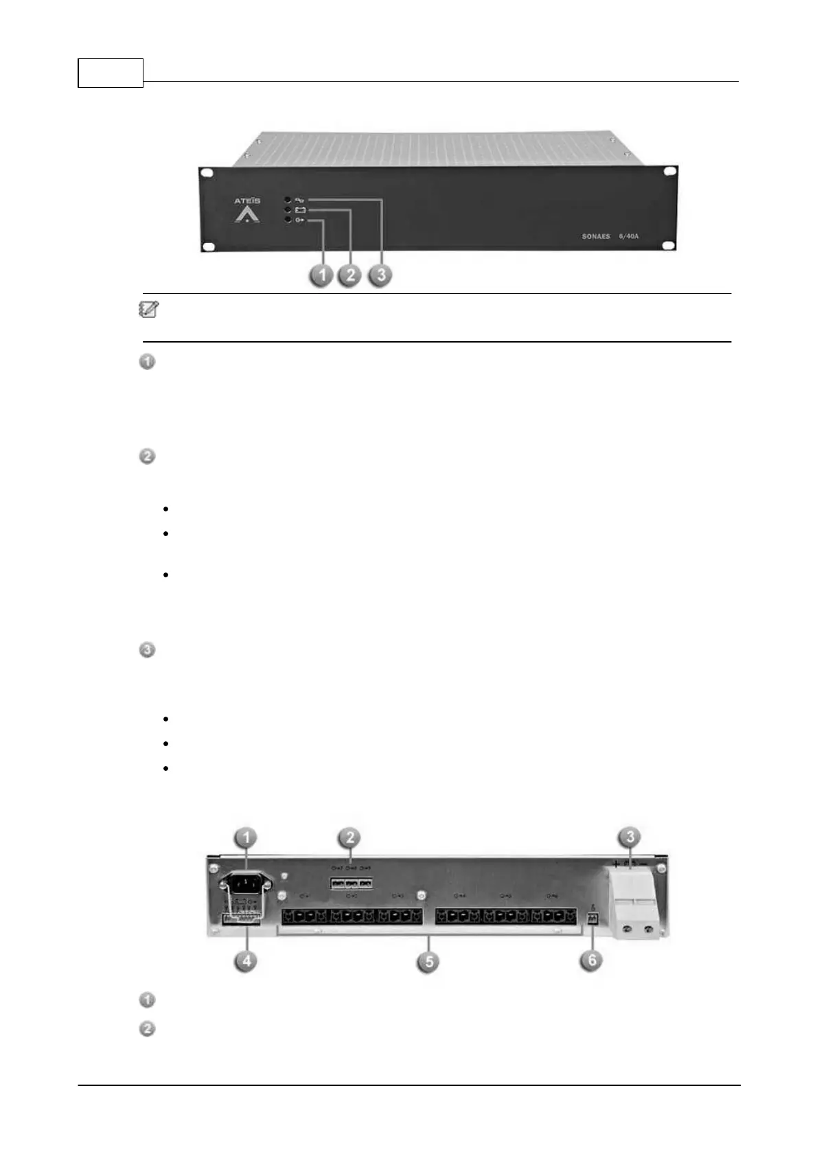
3.5.1.1 Front Panel
When the 3 LEDs light up in green, it indicates that your apparatus is in correct operation. Here
are the possible circumstances of facing detected fault with corresponding LED.
Output voltage fault:
It is signalled by a yellow LED and it's available on dry contact (fail-safe) for remote monitoring.
If there's no voltage on one or more output, all the five outputs are checked. Each dry contact is
with a three pole SPDT switch (C-NC-NO), allowing 1A @ 24Vdc or 0,5A @ 120Vac.
Battery fault (back-up source):
It is signalled by a yellow LED and it's available on dry contact (fail-safe) for remote monitoring.
If the battery voltage < 21,6V ±3 %.
If the internal impedance is too high (test every 4 hours maximum on a charged battery). The
impedance limit value is 50 mW±10 %.
If the battery isn't under operation, the system shall continue proceeding the following manner:
every 30 seconds for the first 20 minutes after commissioning and every 15 minutes after. As
soon as a fault is detected, the test shall be continue proceeding every 30 seconds until 20
minutes after the fault disappears.
Mains fault (normal source):
It is signalled by a yellow LED and it's available on dry contact with delay (fail-safe) for remote
monitoring.
If the mains is not serve or < 195 V.
If the mains fuse is blown.
If the charger is faulty.
3.5.1.2 Real Panel
Main power socket
Auxiliary output terminals
 Loading...