teaching interface, calibrate the first orientation point. Using the same method to calibrate the second pose
point, be sure to make sure that the angle formed by the three points is a right angle. Here you can use the
position movement on the teach interface to help calibrating the orientation point.
The Delete button function is to delete the selected waypoints in the list on the left.
After calibrating the required waypoints, you can calibrate the position parameters and orientation
parameters of the end tool through these waypoints. Select Tool Calibrate Mode option, then, Kinematics
Calibrate button is enabled, the table on the left change into multi-select mode, select a calibrated waypoint,
and click the Kinematics Calibrate button to switch to the interface below.
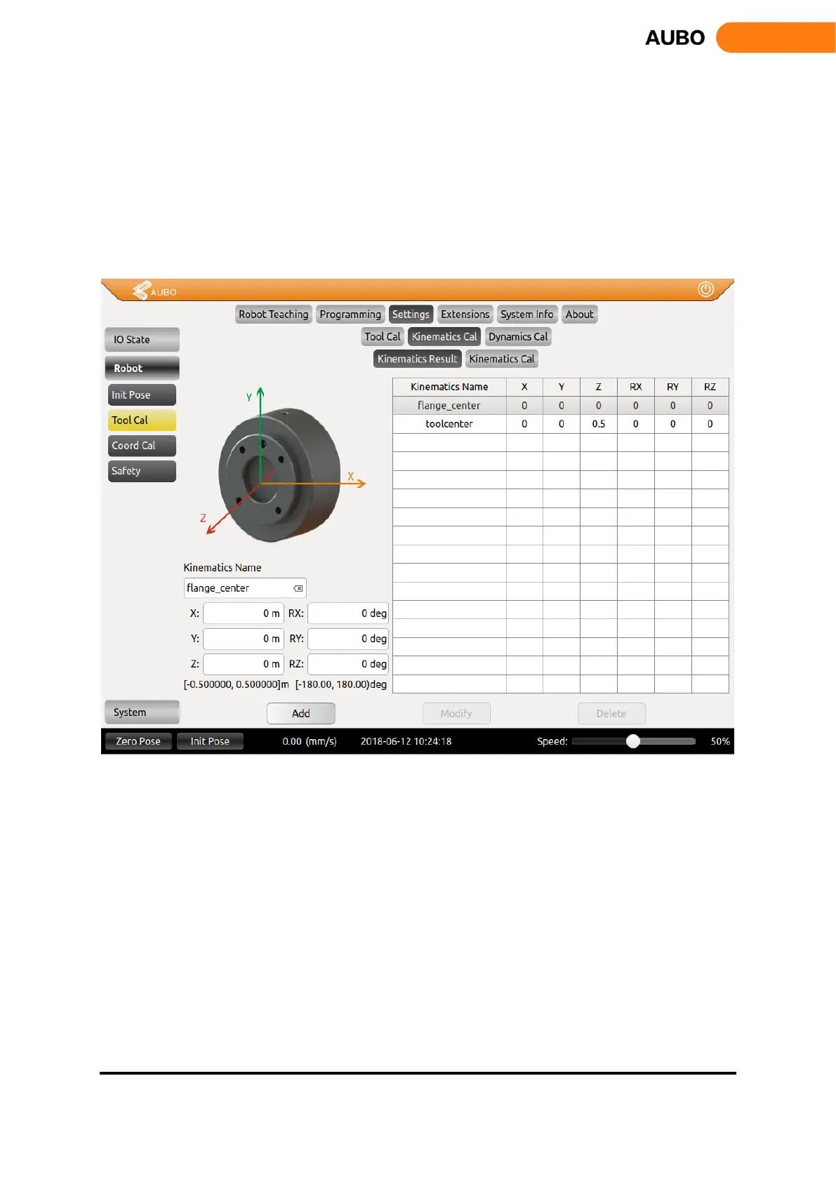
Figure 10.24 Tool Kinematics Calibration
The end tool position parameters and the orientation parameters marked by waypoints are added to the data
display area in the lower left corner. Enter a tool kinematics name and click the Add button to add a tool
kinematic calibration. The above figure also supports the manual write input of tool kinematics parameters.
After manually entering the parameters, also click Add to save the parameters.
When modifying the kinematic parameters of the tool, just like adding the tool kinematics parameters, you
can either calibrate the parameters by the calibration points or you can write the calibration parameters
manually. After setting the parameters, select the kinematic parameters to be modified on the right side of
the figure, and click the Modify button to complete the modification.
When deleting the kinematic parameters of the tool, first select the kinematic parameters to be deleted, and
then click the Delete button to finish the deletion.
Need to pay attention to, kinematics parameter flange_center option is the system default parameters, which
cannot be modified and deleted.