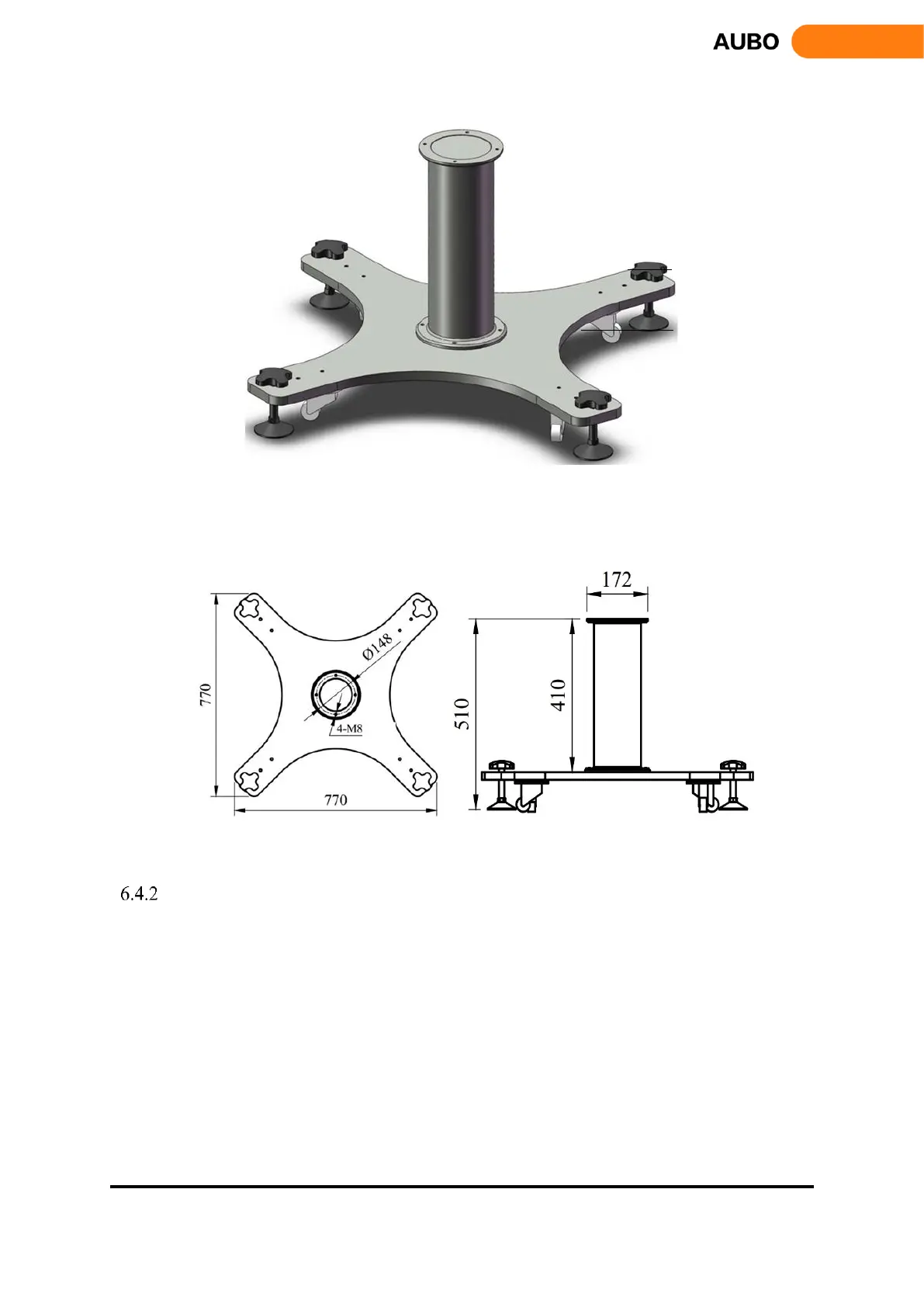
Figure 6.3 Diagram of manipulator base structure
The mechanical dimensions of the manipulator base structure are shown in Figure 6.4
Figure 6.4 Mechanical dimensions of the manipulator base structure (left: plan view; right: front view)
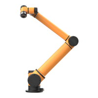
Manipulator Installation
The robot has a function of self-adaption for Installation pose. It can be installed in base, hoisting, mount on
wall or any specific installation method, as shown below: