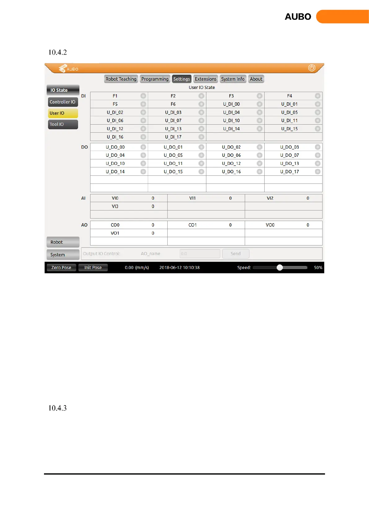
User I/O
Figure 10.19 User I/O
DI and DO are general digital I/O with a total of 16 inputs and 16 outputs that can be used for direct
drive relays and other electrical equipment.
Analog input is used to display the voltage of the external sensor. There are 4 analog input signals:
VI0, VI1, VI2 and VI3, the range is 0V ~ +10V, and the accuracy is ± 1%.
Analog output is used to display the voltage / current value of the output of the interface board. There
are four analog output signals: VO0, VO1, CO0 and CO1, respectively VO0, VO1 output voltage,
CO0, CO1 output current.
output IO control: select the IO, and then enter the corresponding value in the text box, where DO
have 0 and 1 two states, AO: the voltage output range of 0V ~ +10 V, the current output range of 0mA
~ 20mA (recommended input 4mA ~ 20mA current value), click 【Send】 button, the
corresponding IO is set to the default value.
Tool I/O Tab
This section introduces the setting of I/O interface provided by the teach pendant. For the detailed description
of the interface, please refer to electrical interface Manual. I/O settings panel includes tool I/O tab, controller
I/O tab and PLC I/O tab.