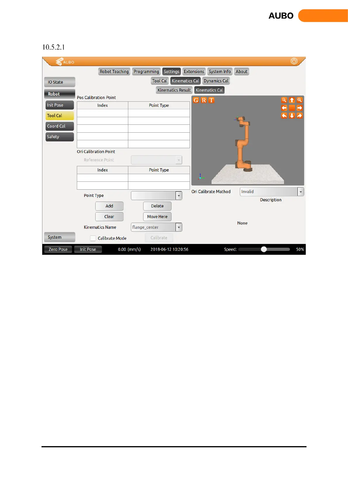
Tool Kinematics Calibration
Figure 10.23 Tool Kinematics Calibration
The tool kinematics calibration consists of two interfaces. The figure above is the tool kinematics point
selection interface. Tool kinematics parameters consist of end-effector position parameters and orientation
parameters. Calibration position parameters need to be greater or equal to 4 waypoints, and calibration
orientation parameters need to have only two waypoints.
The position calibration needs to add a position reference point (used as the origin of the end tool when
calibrating the orientation). Before calibrating the kinematic parameters of the tool, make sure that the arm
has been installed with the tool. First, calibrate the reference position, select the Point Type as Pos Calibration,
click the Add button to enter the teaching interface, and calibrate the reference position by hand guiding or
teaching interface. Position calibration requires at least 4 waypoints to determine the parameters. After that,
you only need to change the orientation and then add three waypoints while keeping the reference point (the
end tool relative to the coordinate system of the base) unchanged. At the final calibration of the 4 waypoints,
ideally the center point of the 4 waypoints is on the sphere center and in the middle of the true end of the
tool.
The orientation calibration needs to calibrate the reference position (i.e., the first point of position
calibration). The principle of orientation calibration is that the reference position is the origin of the end tool
coordinate system. The ray formed by the origin and the first orientation calibration point is the positive half-
shaft of X-axis, the ray formed by the origin and the second orientation calibration point is the positive haft-
shaft of Y-axis, ensure that the angle formed by the three waypoints is at right angles. During the calibration
process, move to the reference position first, select Point Type as Ori Calibration, and click Add to enter the