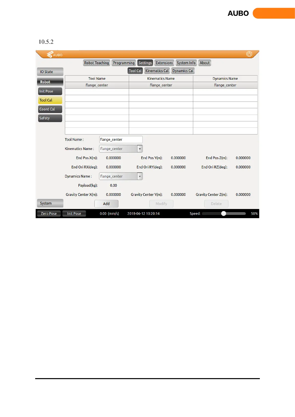
Tool Calibration
Figure 10.22 Tool Calibration
Tool calibration consists of two parts: kinematics calibration and dynamics calibration. A tool consists of
kinematic properties (kinematic parameters that constrain tool end trajectory) and dynamics properties
(Constraints on the dynamics, such as speed and acceleration, of a manipulator with a load).
The tool calibration in the above figure is divided into three calibration interfaces: Tool Calibrate, Kinematics
Calibrate and Dynamics Calibrate.
After calibrating the kinematic and kinematic parameters of the tool, enter the tool calibration interface,
select a kinematic and dynamics attributes for the tool, enter the name of the tool, and then add the tool.