End-effector I/O interface
There is a 8-pins mini connector on end-effector, which electrical error is about±10%, to provide power
and control signals to specific tools (Holder for example) used in the end. Wiring as shown below.
Figure 8.31 connecting cables
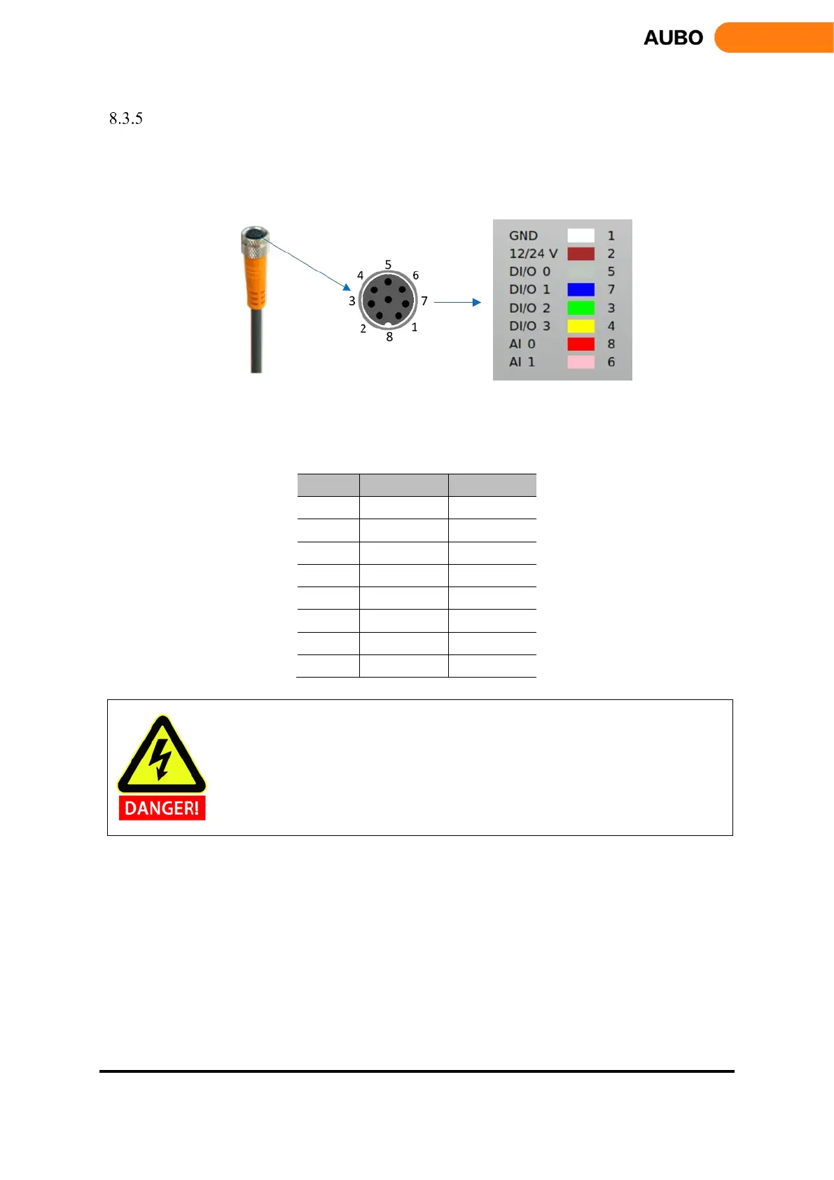
The eight wires inside the Lumberg RKMV 8-354 industrial cable have different colors. The different colors
designate different functions, see table below:
When connecting the tool and the holder, ensure that there is no danger when interrupting
the power supply, such as dropping the workpiece from the tool.