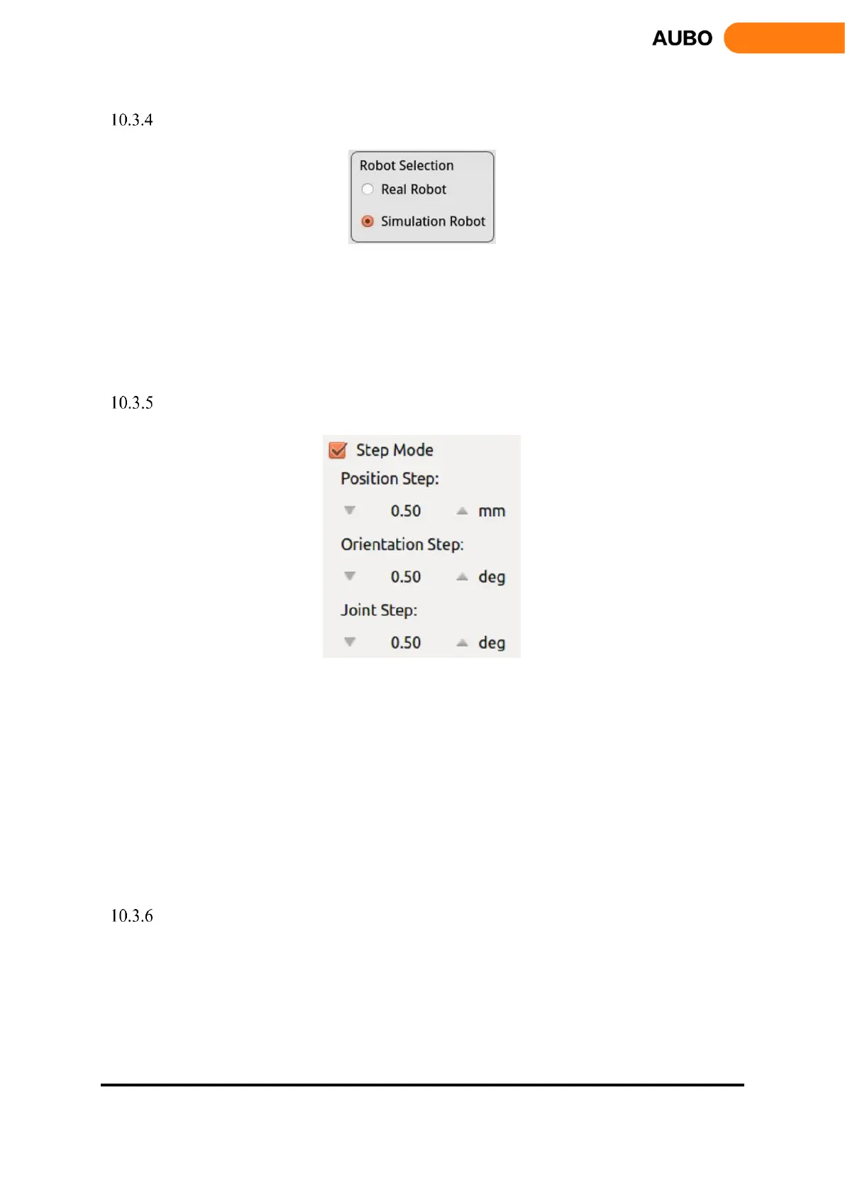
Simulation/real control switch button
Figure 10.7 Robot mode selection.
When "Real Robot" is selected, the teach pendant will control the robot manipulator in real time.
When "Simulation Robot" is selected, the 3D manipulator model operates but the real robot won’t move.
To finish a program, users can test whether the procedure is right, firstly, by simulation to improve the
safety of the robot's procedure.
Step Mode Control
Figure 10.8 Step mode control.
To improve the control accuracy and flexibility, it is necessary to increase the step mode control to allow the
controlled variable change precisely in a stepwise manner.
Use step control mode by activating step mode.
Click the button on both sides of input box to adjust the robot’s step length.
Position step indicates the step length of the end position movement, unit: mm, range:0.1-10.00mm
Orientation step indicates the step length of the end pose movement, unit: deg, range:0.1-10.00deg
Joint Step indicates the step length of the joint movement angle, unit: deg, range:0.1-10.00deg
Step mode control is valid to control the end position/orientation and joints only.
Position control
The end of manipulator is based on the base coordinate system, the end coordinate system or the user-defined
coordinate system to control robot movements. The end of manipulator can teach under different coordinate
systems.