©2015-2018 AUBO.All rights reserved.
THE I SERIES STANDARD CONTROL BOX V4.3
There are 100V-240V AC and 48V DC hazardous voltage inside. Non-professionals do not
open the box.
Control box panel
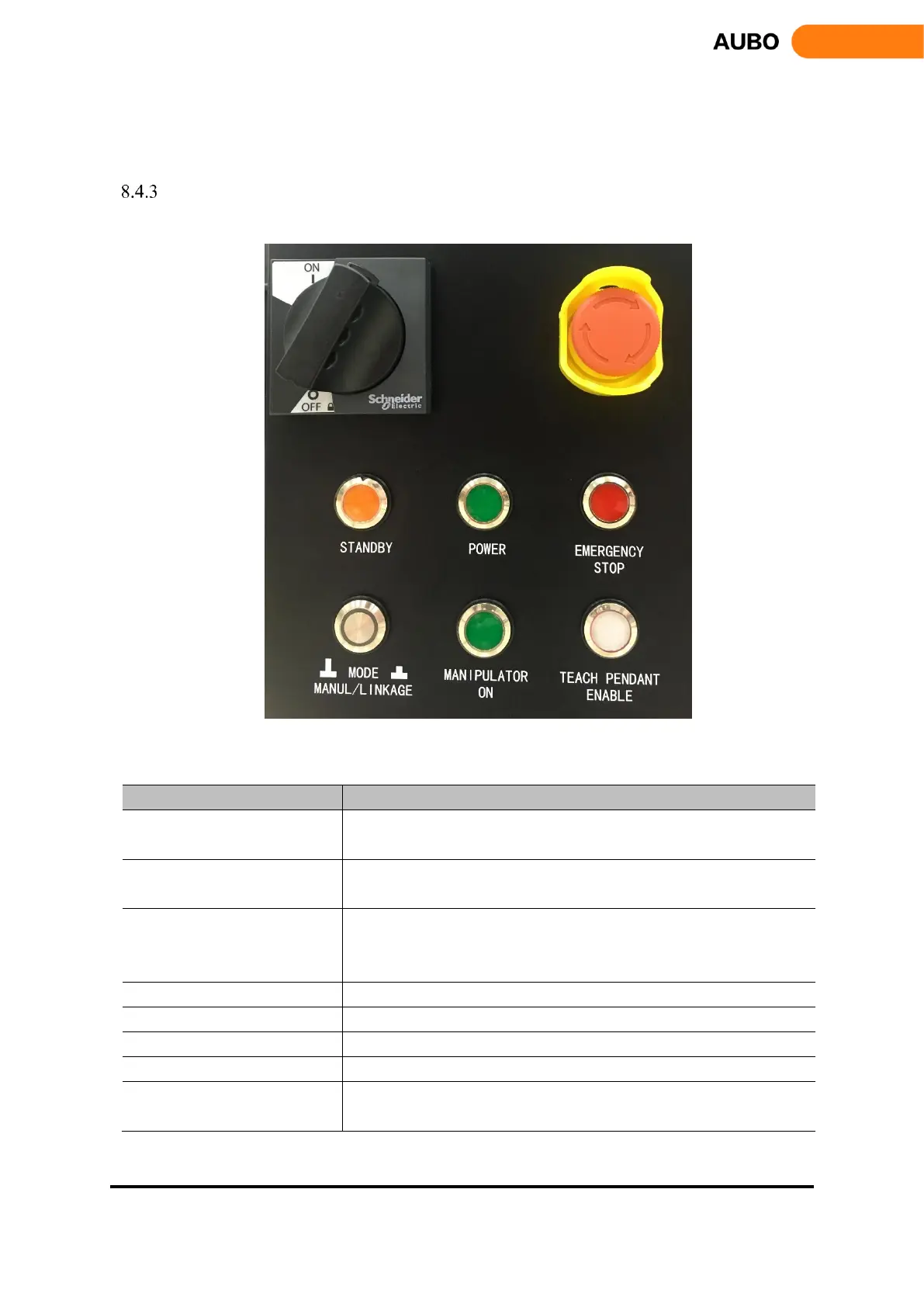
The layout of the control box front panel is shown in figure below
Figure 8.34 Schematic diagram of the control box front panel button
Functions of panel switches, buttons and indicators are shown in the following table:
The main power switches. ON is energized state, OFF is power-off
state.
Emergency stop button. Press to power off the manipulator in emergency
situations.
The indicator lights indicate that the program of control box interface
board initialized completely, press the teach pendant power button to
power on the robot.
The indicator lights indicate that the control box has been powered on.
The indicator lights indicate that the robot is in a state of emergency stop.
Selection of manual and linkage mode. Pressed as linkage mode
The indicator lights indicate when the manipulator has been powered on
Indicator of Teach pendant enable statue. Indicator lights in Manual
mode. In linkage mode, teach pendant disable when indicator off.