EasyManua.ls Logo

AUBO i5 - Page 53

AUBO i5
181 pages
Print Icon
To Next Page IconTo Next Page
To Previous Page IconTo Previous Page
Loading...
©2015-2018 AUBO.All rights reserved.
Page 51
THE I SERIES STANDARD CONTROL BOX V4.3
1. Never connect safety signals to unsafety PLC which is not in correct safety level
2. Be sure to separate the safety I/O signal with normal I/O signal
3. All safety-related I/O are dual-channel which can ensure a signal fault cannot cause
the losing of safety function.
4. Ensure to check the safety function before using the robot, and the safety function
must be tested regularly.
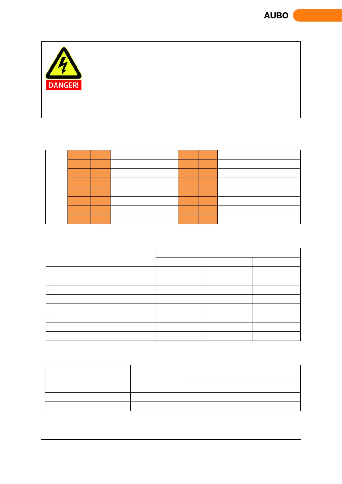
The safety I/O are orange color in the external panel of the control box. The safety functions are defined as
following:
Input
SI00
SI10
External Emergency Stop
SI04
SI14
Enabling Device
SI01
SI11
Safeguard Stop
SI05
SI15
Operational Mode
SI02
SI12
Reduced Mode Input
SI06
SI16
Hand Guiding Enable
SI03
SI13
Safeguard Stop Reset
SI07
SI17
System Stop Input
Output
SO00
SO10
Robot Emergency Stop
SO04
SO14
Not Reduced Mode
SO01
SO11
Robot Moving
SO05
SO15
System Error
SO02
SO12
Robot Not Stopping
SO06
SO16
BACKUP (Unavailable for User)
SO03
SO13
Reduced Mode
SO07
SO17
BACKUP (Unavailable for User)
Safety related electrical inputs
Safety-related electrical outputs
Safety Input Functions
Worst Case
Detection time
Power off time
Response time
External Emergency Stop
100ms
1200ms
1300ms
Safeguard Stop
100ms
——
1200ms
Reduced Mode Input
100ms
——
1200ms
Safeguard Stop Reset
100ms
——
1200ms
Enabling Device
100ms
——
1200ms
Operational Mode
100ms
——
1200ms
Teach Pendant Emergency Stop
100ms
1200ms
1300ms
System Stop Input
100ms
——
1200ms
Safety Output
Worst case
responding time
Safety Output
Worst case
responding time
Robot Emergency Stop
1000ms
REDUCED MODE
1000ms
Robot Moving
1000ms
NOT REDUCED MODE
1000ms
Robot Not Stopping
1000ms
SYSTEM ERROR
1000ms

Table of Contents

Related product manuals