Azbil Corporation Introduction
Model MGG10C/14C - MagneW FLEX+/PLUS+ Converter 1-7
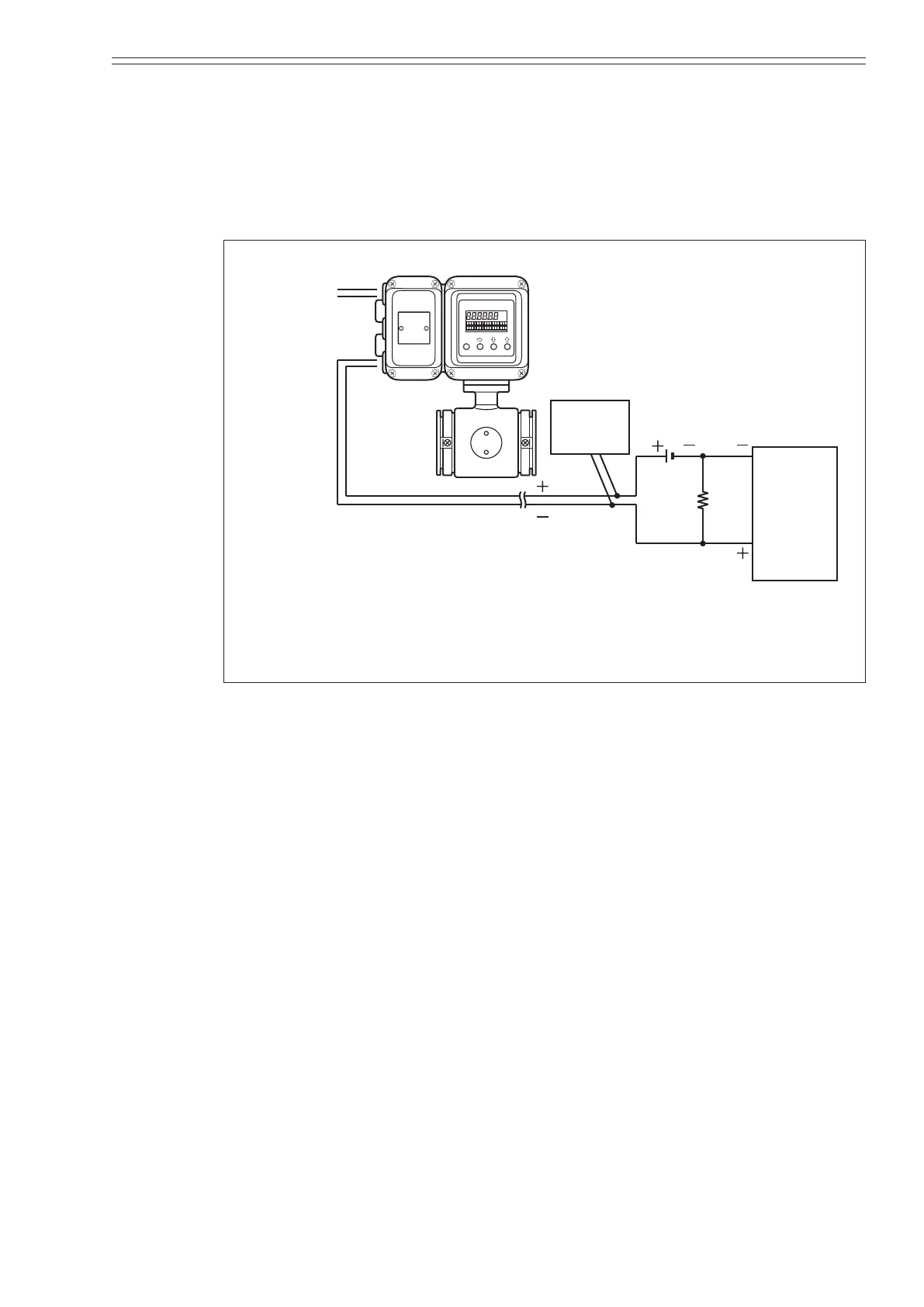
System conguration WITH the SFC or HART communication function
with the external power supply
Figure 1-5 shows a sample system conguration in which the instantaneous ow rate
measured by the unit is output with a 4 to 20 mA DC analog signal.
In order to enable communications, a DC power supply and a resistance of 250W or
more must be installed on the receiving side.
C or DC
Smart
communicator
4 - 20 mA
analog output
250Ω
resis-
tance
Host
control
system
(1 - 5 V
input)
SFC or
HART
DC24V power supply
Figure 1-5 System conguration for analog output WITH the communication
function (example setup)
Smart Electromagnetic Flowmeter (device)
• Measures ow rate and outputs an analog signal instantaneous ow rate.
Smart Communicator (SFC):
• Communicates with the device to read data and change the device settings.
• The SFC version must be V7.0 or later.
HART Communicator:
• For the HART communications by the HART 375 communicator, the neccesary DD
le needs to be downloaded.