Azbil Corporation Installation
Model MGG10C/14C - MagneW FLEX+/PLUS+ Converter 2-17
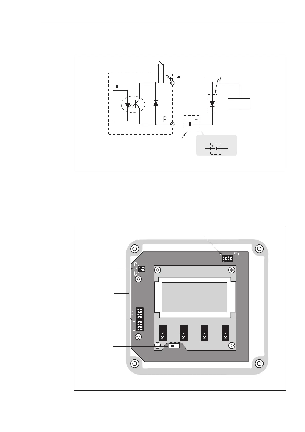
Pulse output wiring
The pulse output is an open collector output.
Pay close attention to voltage and polarity when wiring.
200mA max.
Load
Avoid this polarity
External
power supply
30V max.
Figure 2-16 Wiring diagram for pulse output
~ Note
Check and conrm that the polarity of the wiring is correct. Incorrect polarity may
cause damage to the equipment.Use an external power supply that meets the voltage
and capacity specications. Pulse may be output when the power is turned ON or
OFF. Pulse output protection circuit causes voltage drop. Some counters may not
pick up the pulses due to this voltage drop. In such case, turn On S6 switch. Refer to
the Figure 2-17.
Empty detection function switch
Wr
ite
tion
d
ommnication
S6 ON
Pulse output
protection
circuit
Figure 2-17 Switch locations on main card