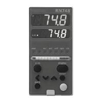
Using the display panel Azbil Corporation
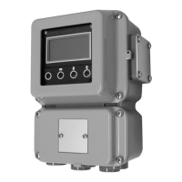
4-2 Model MGG10C/14C - MagneW FLEX+/PLUS+ Converter
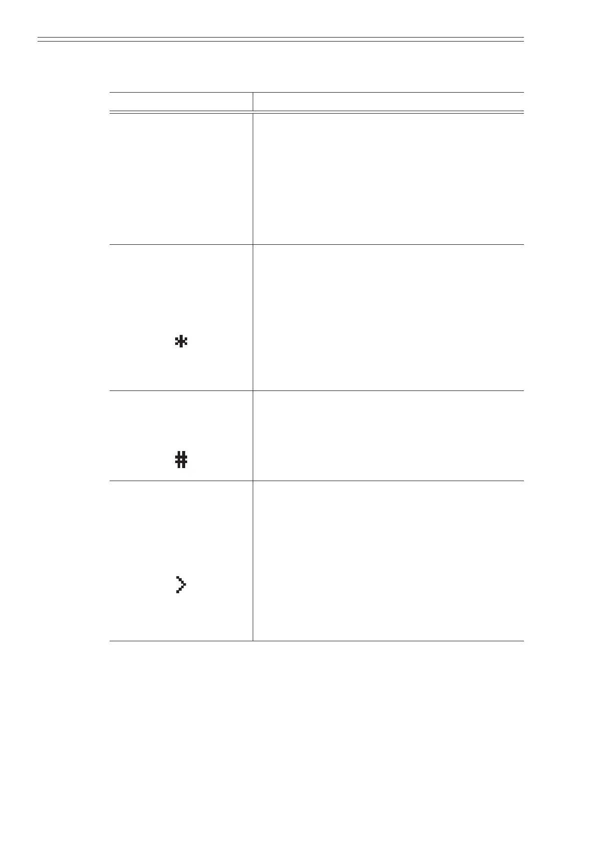
The following table describes the functions available in each mode.
Table 4-1 Mode functions
Mode Description
MEASURING MODE
This is the normal operational mode and indicates the
measuring status.
Each time the MEASURING MODE is selected,
data is written into memory. Settings entered in
other modes are held in temporary memory for two
minutes, but will return to the previously saved value
unless the MEASURING MODE is selected to save
the data. The only exception is the counter, which is
always saved into memory immediately.
BASIC SETUP MODE
Mode indicator:
This mode is used to change data settings that must
be recorded or changed frequently. These settings
include:
TAG NO.
Damping time constant
Display select
Auto zero
Flow rate range
Detector data
Built -in counter reset/preset
ENGINEERING MODE
Mode indicator:
This mode is used to change data settings that are
used less frequently. These settings include:
Function setting
Flow rate range
Pulse data
Fail safe mode setting
MAINTENANCE MODE
Mode indicator:
This mode is used when adjustment or verication
is required for regular maintenance of the system
or when troubleshooting the system. This mode
includes:
Shipping information
Output adjustment
Gain adjustment
This mode is further divided into the following two
modes:
OUTPUT CHECK MODE
CALIBRATION MODE