Azbil Corporation Installation
Model MGG10C/14C - MagneW FLEX+/PLUS+ Converter 2-13
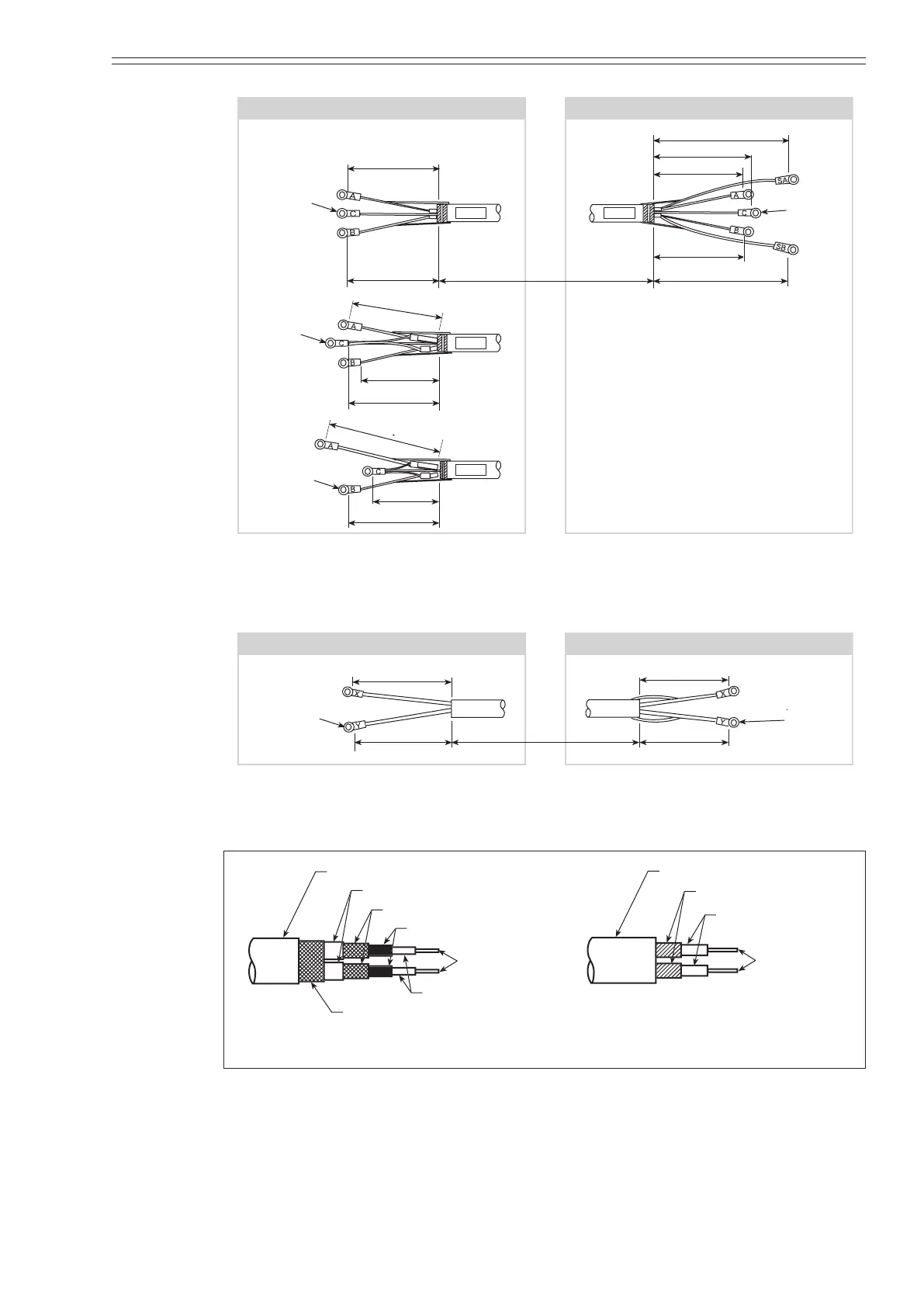
Detector side Converter side
mm (inches)
To M4
Screw
To M4
Screw
To M4
Screw
To M4
Screw
Model A
Model B
60 (2.36)
60 (2.36)
60 (2.36)
60 (2.36)
60 (2.36)
60 (2.36)
40 (1.57)
70 (2.76)
90 (3.54)
65 (2.56)
L 90 (3.54)
60 (2.36)
65 (2.56)
Figure 2-11 Signal Cable Dimensions
Detector side Converter side
mm (inches)
60 (2.36)
60 (2.36)
70 (2.76)
70 (2.76)
To M4
Screw
To M4
Screw
L
Figure 2-12 Excitation Cable Dimensions
er
he
Inner
he
Inner
hiel
Conductive tube
Black
n
ive wir
In
l
Cloth ta
In
l
n
ive wir
nal cable
Ex
i
i
n
l
Figure 2-13 Signal and excitation cable construction
~ Note
Strip the conductive tubing (black) down to the ends of the inner shields on the
conductive wires for terminals A and B of the signal cable.