10. Communicator Touch Panel
M
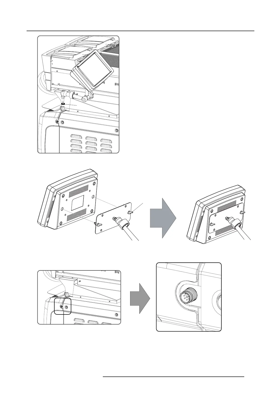
Image 10-4
3. P lace the touch p anel interface on the m ounting plate of the swivel a rm and fasten the two wing nuts (W) as illustrated.
W
Image 10-5
Mount touch panel
4. Connect the circular plug of the m ulti cable with the circular socket at the rear side of the D P xK B LP series projector.
Image 10-6
5. A ttach the multi cable to the swivel arm using the two Velcro strips.
6. Connect the DC plug, the RJ45 E thernet plug and the D-SUB plug into their respective sockets on the touch panel interface.
R5906753 DPXK BLP SERIES 20/11/2017
115

 Loading...


