4. Physical installation projector
Y Δ
1
2
3
4
5
6
B
A
C
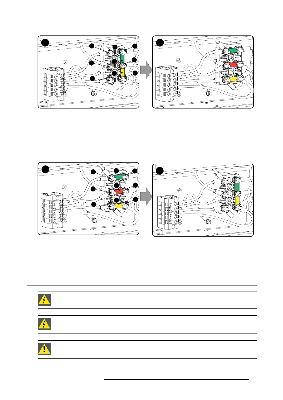
Image 4-9
Υ to Δ connection
2. Take off the mounted lins (A, B and C). Two links abov e each other or mounted b etween the upper and middle pin (A , B) and one
link between the middle pin and lower pin (C).
3. Mount the links horizontally on the pins.
4. Turn a nut on each pin and secure with a torque w rench set to 7.5 Nm.
HowtoswitchfromaΔ-connection to Υ-connection
1. L oosen the top nuts on the Υ/Δ configuration bloc k (1 to 6).
Y
Δ
1
2
3
4
5
6
A
B
C
Image 4-10
Δ to Υ connection
2. Take off the mounted links (A, B and C).
3. Connect the right pins together. P lace 2 links between the upper pin and the m iddle pin (A, B)and 1 link between the m iddle pin
and the lower pin (C).
4.4 Connecting the DPxK-17/23BLP with the power net
WARNING: The total electrical installation should be protected b y an appropriate rated and readily accessi-
ble disconnect sw itch, circuit breakers and ground fault current interrupters. The installation shall be done
according to the local electrical installation codes.
WARNING: Make sure that the voltage range of projector matches with the voltage of the local power net.
CAUTION: The cross-sectional area of the conductors in the Power Supply Cord shall be not less than 4 mm
2
or AWG 10
R5906753 DPXK BLP SERIES 20/11/2017 31