4. Physical installation projector
Necessary tools
• Flat torque screw driver
• Adjustable wrench
Necessary parts
•Certified power supply c ord 4.0 mm ², 10AWG, min. 300V, diam eter between 11 mm and 21 mm
• Circuit breaker maximum 40A
How to connect
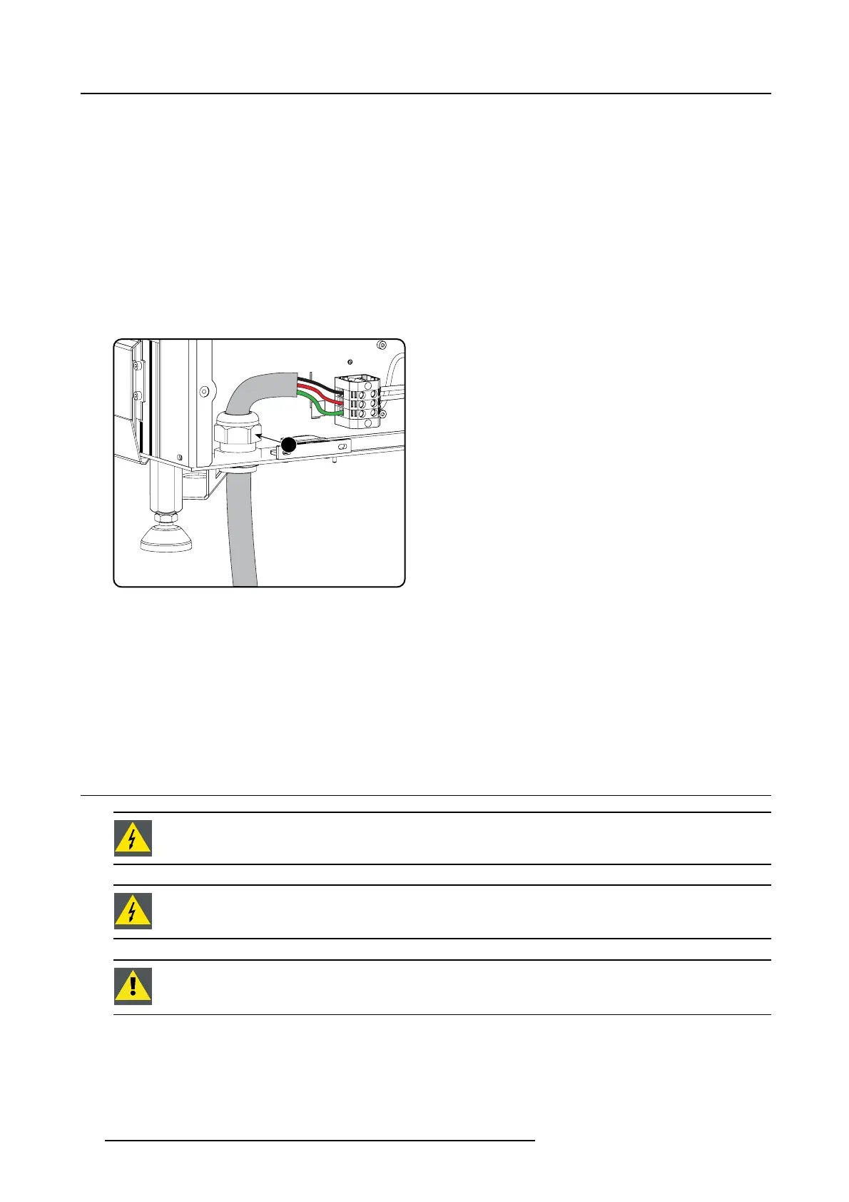
1. Remove the back cover.
2. Remove the power input c over.
3. L oosen the cable gland fixation ring (1).
Note: The c able gland ( 1) is specified for cables with a diameter between 11mm and 21m m.
1
Image 4-11
Power cable connection
4. P ush the s tripped power supply cable through the cable gland. When us ing a flexible power cord, ma ke sure that each conductor
end is provided with a n end sleeve.
Fix the cable in the cable gland by securing ring 1 w ith an adjustable wrench.
5. C onnect the power cord with the term inal barrier strip. Us
eaflat torque screw dr iver set to 2Nm.
Always con nect the ground wire (PE) with the connector indicated with PE on the terminal barrier s trip.
Warning: Always connect first the PE wire .
6. Reinstall the power c onnection cover and the back cover.
4.5 Connecting the DPxK-36BLP with t he power net
WARNING: The total electrical installation should be protected b y an appropriate rated and readily accessi-
ble disconnect sw itch, circuit breakers and ground fault current interrupters. The installation shall be done
according to the local electrical installation codes.
WARNING: Make sure that the voltage range of projector matches with the voltage of the local power net.
CAUTION: The cross-sectional area of the conductors in the Power S upply Cord shall not be less than 4 mm
2
or AWG 10.
Necessary tools
• Flat torque screw driver 4 mm
• Adjustable wrench
32
R5906753 DPXK BLP SERIES 20/11/2017