5. Physical installation top cooler
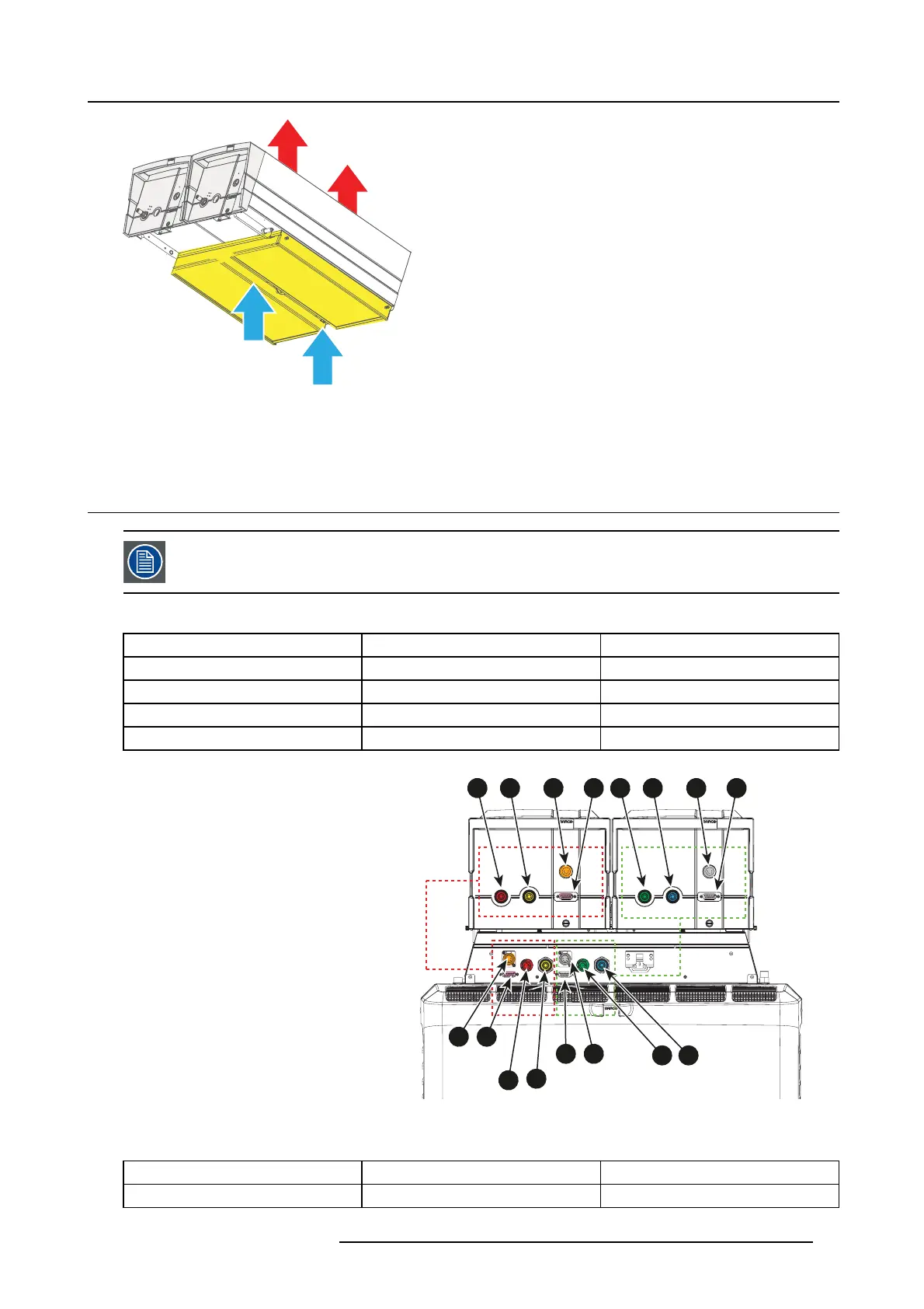
Image 5-20
3. P lace the cover plate back on its location and drive in b oth fixation screws by hand.
Note: Please, don’t use any tool! Only hand tighten these screws.
5.7 Cabling and tubing
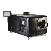
Always conn ect t he right cooler w ith right group of connectors at the backside of the projector. Connect the
left cooler with the left group of connectors at the backside of the projector.
Tubing
From projector connector plate To cooler
Tube 1 1f 1m
Tube 2 1m 1f
Tube 3 2f 2m
Tube 4 2m 2f
1m 1f 1a 1b 2m 2f 2a 2b
1f
1m
2f 2m
1a 1b
2b 2a
Image 5-21
Cabling & tubing
Cabling
From projector connector plate To cooler
XLR c able 1 1a 1a
R5906753 DPXK BLP SERIES 20/11/2017 49