10. Communicator Touch Panel
A Touch screen
B
Communication pan el
C
Knob to op erate central swivel clamp
D
Base of swive l arm
E
Power input 12 VDC, 1.5A
F
RS232 port (sub-D)
G E thernet port (RJ45)
CAUTION: For more information about the use of the Communicator Touch Panel, consult its user guide.
10.2 Installation of the touch panel interface
Necessary tools
• 17 mm wrench
• 10 mm wrench
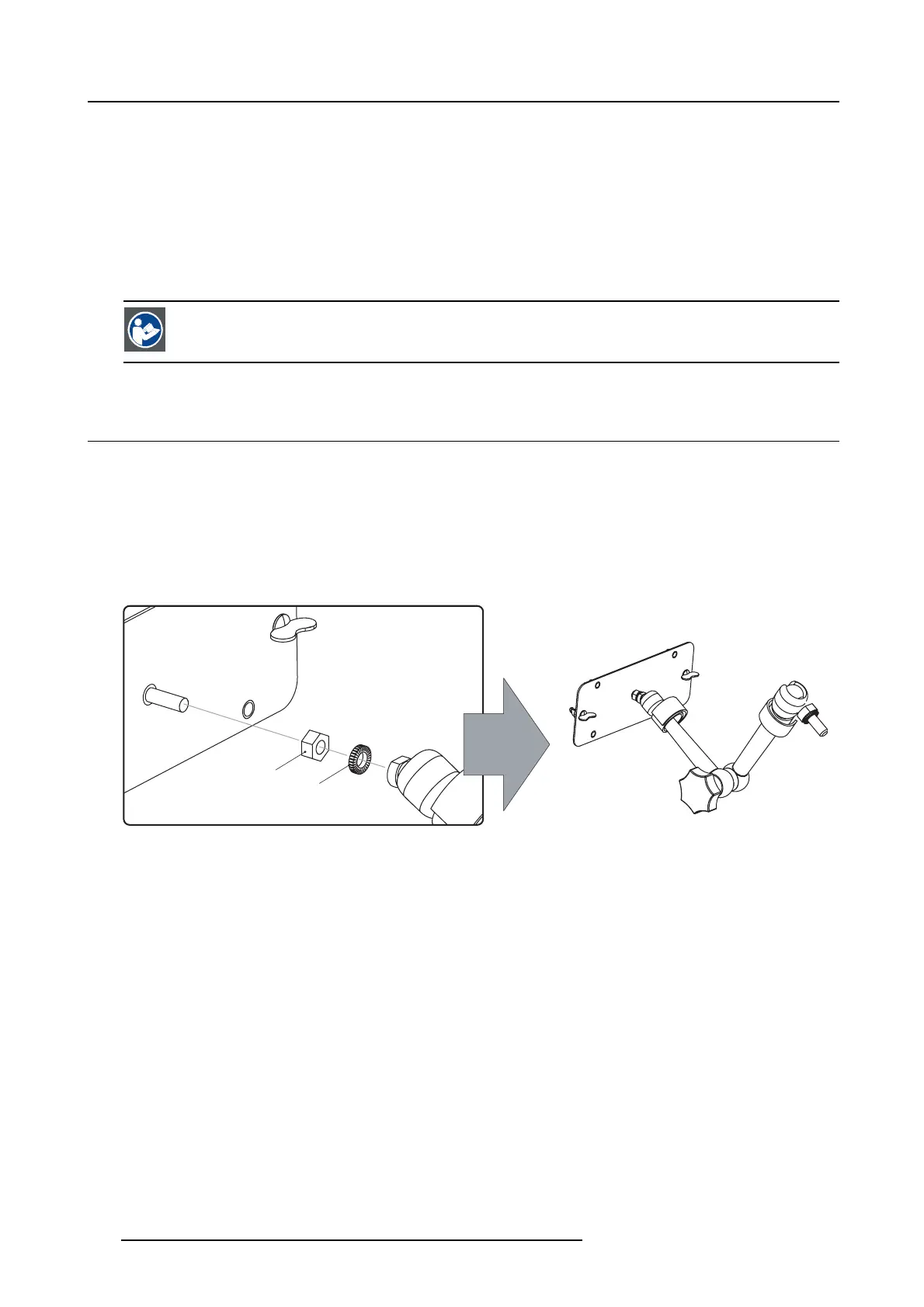
How to install the touch panel interface
1. A ss emble the mounting plate and the sw ivel arm together as illustrated. First plac e the nut (N) upon the rod of the mounting
plate, then add the lock w asher (L), then fasten the mounting plate and the swivel arm together. When the arm is mounted, turn
nut (N) against t he arm to secure the position.
N
L
Image 10-3
Assemble swivel arm
2. S lide a washer (M) over the base of the swivel arm and Insert the base of the swivel arm into the mounting hole at the top of the
DPxK BLP series projector as illustrated.
114
R5906753 DPXK BLP SERIES 20/11/2017

 Loading...


