8. Input & communication
8.7 Cinema Controller of the DPxK-xxBLP
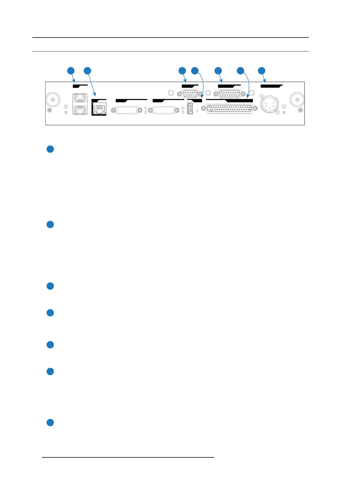
Location of the communication ports
PERIPHERAL PORT
WAN
LAN
GENERAL INTERFACE I/0USB 2.0DVI IN A
DVI IN B
RS 232 IN 3D INTERFACE
1 3 5 72 64
Image 8-9
Functionality
1
Local Area Network (LAN: 10/100/1000 base-T) port
Local Area Network (LAN : 10/100/1000 base-T) with built-in Ethernet switch (port 1 and port 2). Use for projector c ontrol
and automation. E .g. Touch Panel, content server, ... (not for content streaming!)
As there is a nee d to daisy chain projectors w hen they are on an Ethernet network, an E thernet switch is built in. the
incoming network is hereby available for the internal PC an d for the next device in the chain. In this way a ’star’ network
interconnection ca n be avoided. T he switch used is a stand alone 10/100/1000Mbit E thernet switch. This assures no
influence on the network speed. Furtherm ore, this Ethernet switch remains operational when the projector is in Standby
mode.
The connectors used for these Ethernet po rts are of the type RJ45 , which is c ompatible with standard RJ45 cable connector.
Straight (most common) as w ell as cross linked network cables ca n be used. The 2 por ts are functionally identical. Both
ports are con nected via the projector sw itch (Auto sensing enabled).
2
Wide Area Network (WAN) port
Wide A rea Network (WAN: 10/100/1000 base-T). U se this Ethernet port (reference 2 image 8-9) to connect the network
which contains the DHCP s erver.
The DPxK BLP series projector can be connected to a WAN ( W ide area network) (reference 2 image 8-9). Once connected
to the WAN, users can access the projector from any loc ation, inside or ou tside (if allowed) their com pany network using the
Communicator software. This software locates the projector on the network if there is a DHCP server or the user c an insert
the correct IP-address to access the projector. Once accessed, it is po ssible to check and m anipulate all the projector
settings. Remote diagnostics, control and monitoring of the projector can then becom e a daily and very simple oper ation.
The network connectivity allows detection of potential errors and consequen tly improves service time.
3
RS232 IN port
This female DB-9 c onnector allows you to use a standard serial cable up to 10 meter to connect the touch panel interface
with the projector. Note that the RS 232 protocol is used on this connection.
4
USB O UT port
The Cinema Controller is equipped with a USB por t, type “A” c onnector, (reference 4 image 8-9) whic h can be used to power
handheld devices within USB spec (M AX 500mA/5V]. N o other functionality supported (Future expansion). The USB OUT
port remains operational in Standby mode.
5
3D INTERFACE port
3D interface po rt (reference 5 image 8-9. Can be used to connect external 3D devices to the pro jector. All signals necessary
for 3D pro jection can be provided via this co nnector. The 3D interface po rt is disabled if the projector is in Standby mode.
6
GENERAL PURPOSE INPUT/OUTPUT (GPIO) port
This 37 pin connector ( reference 6 image 8-9) can be used to send or receive trigger signals from other devices. These
input/output pins can be programmed by m acros created with the C om municator software. See us er ’s guide of the
Communicator, s ection Macro editor, for m ore information about this functionality. Note that the General Pu rpose Inputs
accept 24 volt maximum. The GP IO remains operational when the projector is in Standby mode. So, if t he factory predefined
macro to wak e up the projector is assigned to one of the free GPI input pins the projector c an be awakened via GPIO.
Enter or leave Standby mode can also be done with GPIO via two predefined M acros (not editable).
7
PERIPHERAL port
For future use.
90
R5906753 DPXK BLP SERIES 20/11/2017