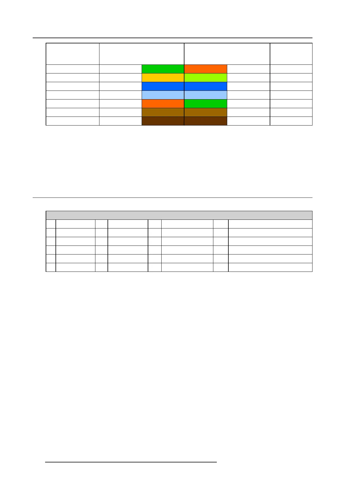
17. Pin configurations
RJ-45 P in Number
(Left >Right copper
side)
568A 568B
AES -1-8
2
Green Orange AES 1&2 +minus
3
White/Orange White/Green A ES 3&4 +plus
4 Blue Blue
AES 5&6 +minu s
5
White/Blue White/Blue A ES 5&6 +plus
6
Orange Green AES 3&4 +minus
7
White/Brown White/Brown AES 7&8 +plus
8Brown Brown
AES 7&8 +minu s
568A and 568B may be used interchangeably in a s ystem SO LONG AS both ends of a given cable are terminated the same way.
568A + 568B wiring is a c rossover cable.
568A + 568A wiring is a straight cable.
568B + 568B wiring is a straight cable.
The mapping of the channels is done ac cording to the E thernet wiring scheme a nd gives us 100 O hm per pair.
17.4 Pin configurations of the inputs
DVI-D
DVIINA&B
1RX2- 7
DDC Data
13
nc
19
RX0 Shield
2RX2+ 8
nc
14 +5V 20
nc
3
RX2 Shield
9RX1- 15
GND
21
nc
4
nc
10 RX1+ 16 Hot P lug Detect 22
TMDS Clock Shield
5
nc
11
RX1 S hield
17 RX0- 23
TMDS RXC+
6
DDC Clock
12
nc
18 RX0+ 24
TMDS RXC-
164 R5906753 DPXK BLP SERIES 20/11/2017