16. Color calibration
x
y
G
t
C
t
Y
t
M
t
R
t
B
t
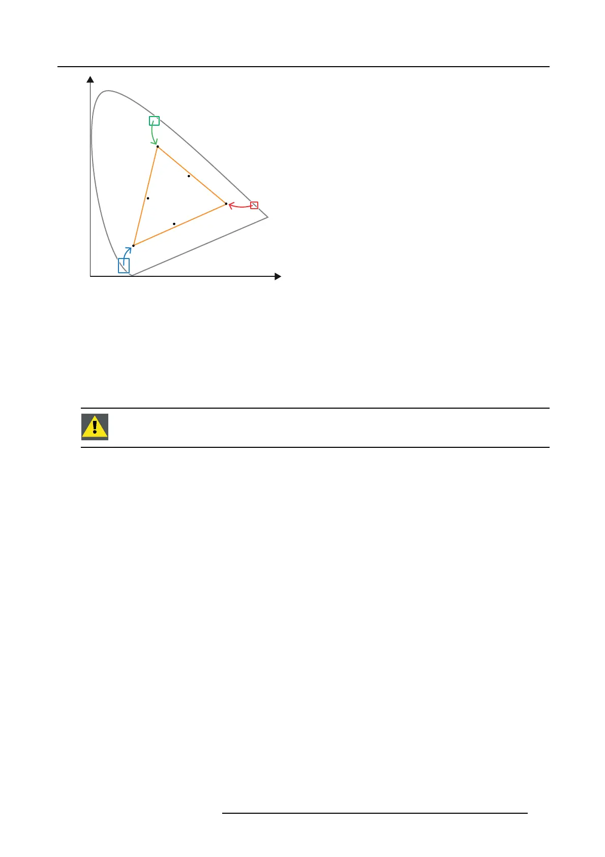
Image 16-2
Correction of native color gam ut towards desired color gamut (electronic correction)
Electronic correction
The electronic correction adap ts the native color gamut towards the desired (target) color gamut (e.g. DC28_DCI_Xenon.TCGD).
This correction is introduced by the DM D d rivers and is also called ‘P7 correction’. The electronic correction takes place once the
MCGD file of the projector is mappe d with the T CG D file of the fi lm.
Influence of aspect ratio
The aspect ratio of the projected image could have a sma ll influenc e upon the m easured x y coor dinates. Therefore, it’s recom -
mended to save the x y coordinates per aspect ratio in separate MCGD files.
CAUTION: P rior to sta rt with co lor gamut calibration ensure that the white point calibration is finalized suc-
cessfully. See "Wh ite point calibration", page 155.
Color gamut calibration procedure
1. Check if the white point calibration is done. If no t see "White point calibration", page 155.
2. S etup the ambient light conditions as it should be during the play out of the movie. (e.g. only the stairs and em ergenc y exit
lighting is switched on).
Note: In an optimal setup less than 1% of light from an y other source than the light from the projector should illuminate the
screen.
3. S eq uentially m easure and enter the xy coo rdinates of the three primary colors (red, green, blue) and full white. Use therefore
the Communicator. Go to Installation > C olor ca libration > M easure native colors. For detailed instructions see user guide of the
Comm unicator.
Caution: Ensure that the correct projection m ode is selected: 2D or External 3D.
Caution: In case of 3D, me asure the x y coordinates once through the left eye glass of the 3D goggles and once through the
right eye glass.
Tip: When using the wizard for w hite po int calibration you can im mediately proceed with the electronic correction.
4. O nc e all xy coordinates are measured and entered proceed by saving all meas ured values into a MCG D file.
Tip: Put in the MCG D file nam e the type of proj
ection mode ( 2D or External 3D) and the aspect ratio (FLAT, SCOPE).
5. M ap the MCGD file with the TCGD file. Use for that the Comm unicator. Go to Installation > Color calibration > Select target
colors. For detailed instructions s ee use r guide of the Communicator.
6. In addition you can check if the co rrected colors comply. Use therefore the Com munica tor. Go to Installation > Color calibration
> Verify corrected colors. For detailed instructions see us er guide of the Commu nicator.
R5906753 DPXK BLP SERIES 20/11/2017
157


 To Next Page