C8000 Battery Testing System User Manual
214 3 Cadex BatteryLab
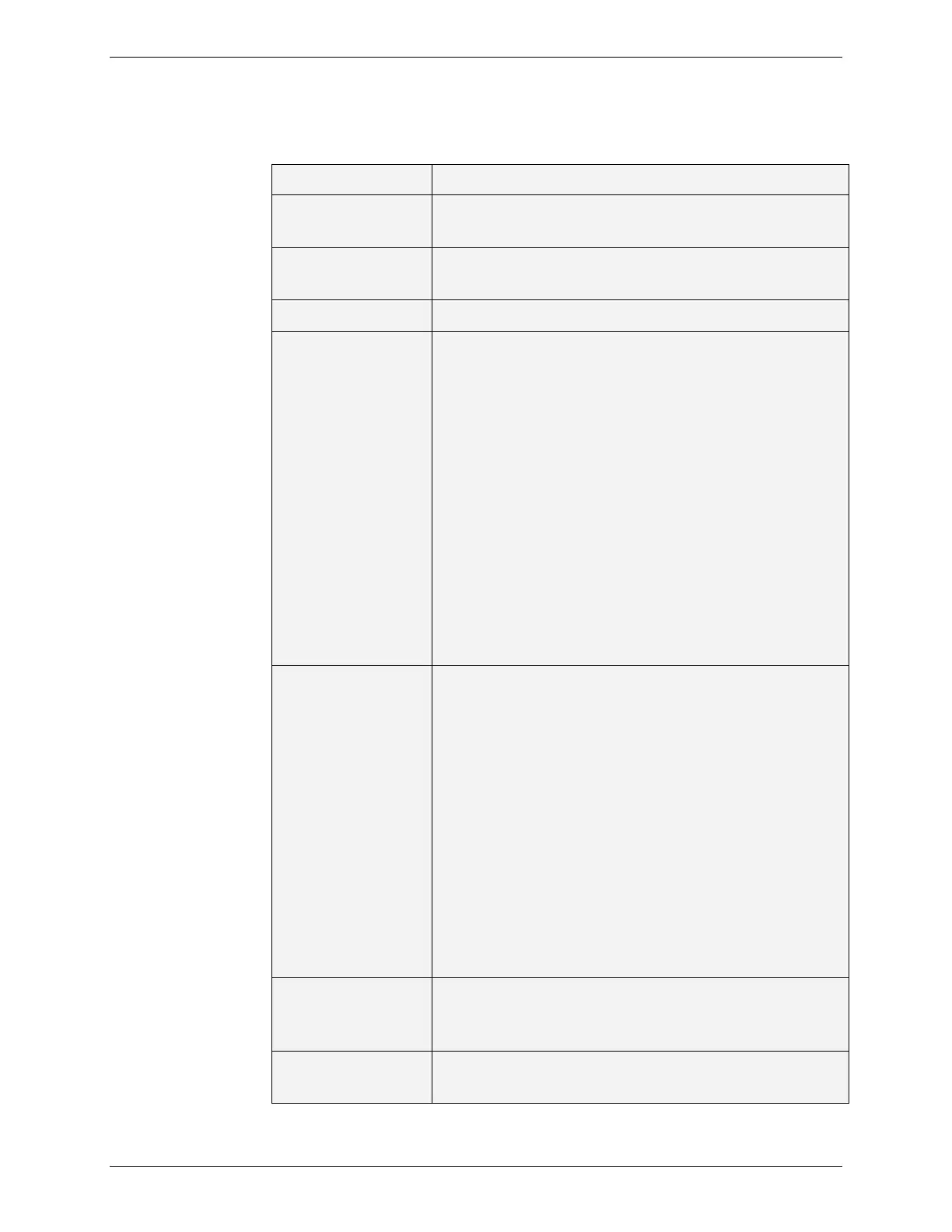
The following table describes the fields in the Load Capture Test
window. (Page 192)
The number of sample points to be captured
(minimum=10, maximum=500).
The sample rate for each point – stated in milli-
seconds with a range of 0.5ms to 30000ms.
The total capture period.
The method of triggering the capture:
No trigger: No trigger is defined. The capture starts
immediately on completing initializing.
Current limit: A current target level is required to
start the capture (requires Trigger Method definition).
Digital Logic: A digital level is required to start the
capture (requires Trigger Method and Trigger Port
definition).
Analog Input Port 4: An analog voltage level is
required to start the capture (requires Trigger Method
and Range definition).
Range: Defines the input voltage range of the analog
port (selectable ranges: 0-5v, 0-10v, 0-15v).
Defines the condition for the Trigger Type parameter:
Trigger High: Reading must be higher than the point
as defined by the Trigger Type parameter.
Trigger Low: Reading must be lower than the point
as defined by the Trigger Type parameter.
Low-> High: Reading must transition from a lower to
a higher reading than the target point defined by the
Trigger Value parameter.
High->Low: Reading must transition from a higher to
a lower reading than the target point defined by the
Trigger Value parameter.
Note: Current is defined in Negative Logic.
The trigger point. Defined as current (mA) for
Current Limit and voltage (mV) for Analog Input Port
4.
The input source that a current is to be captured on.
In-circuit: Selects the internal capture circuit of the
 Loading...