Metering
160 APOLLO
Digital Broadcast Production Console
TFT METERS
The Apollo TFT meter layouts can be
customised in several ways.
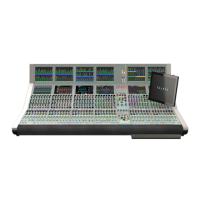
Fig 1 on the right shows an example
layout of a configured TFT meter.
The TFT is divided up into a number of
‘cells’, each of which can be one of a
number of sizes, and can display mono,
stereo or surround meters. Paths that
support dynamics also display gain
reduction meters
Meter cells
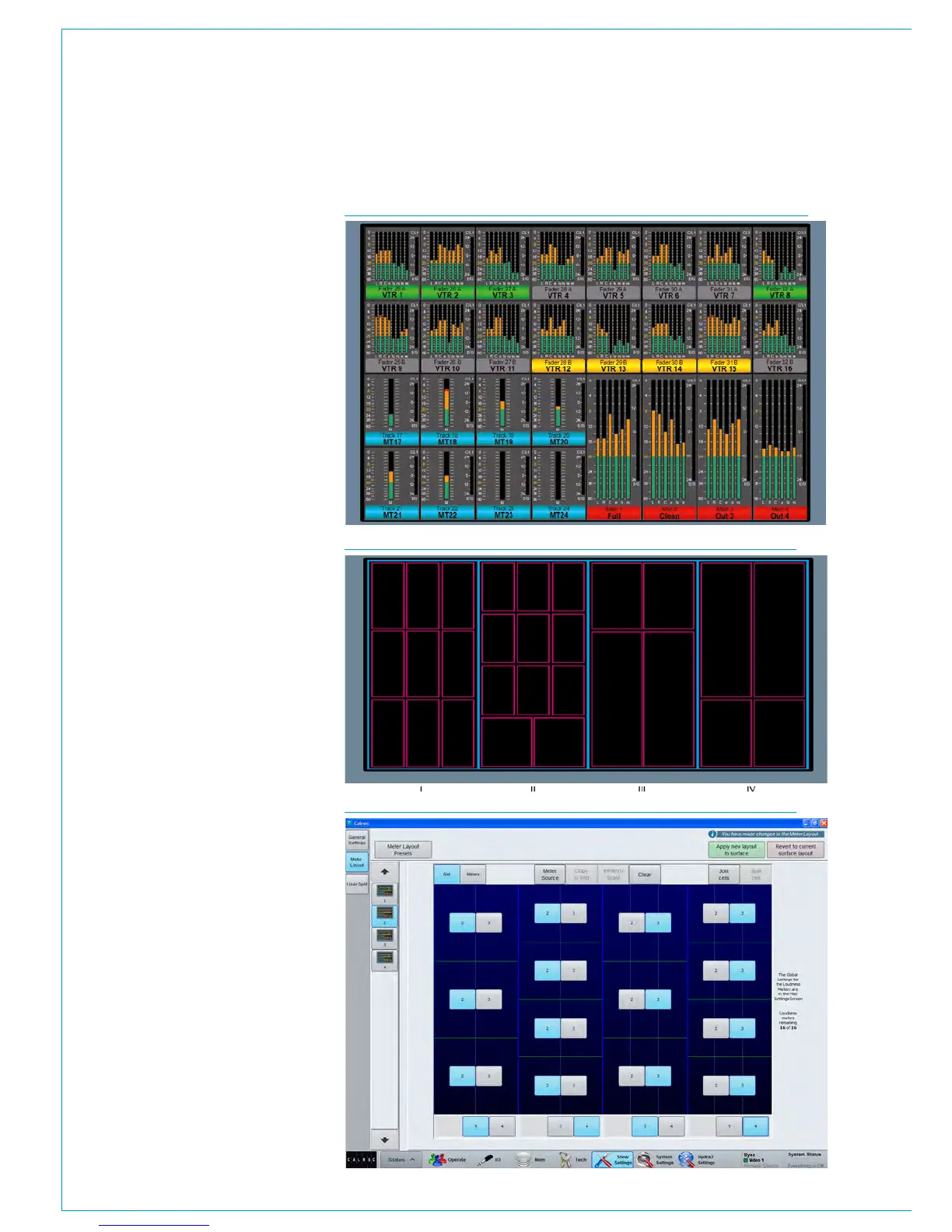
Each TFT meter is divided into four
vertical sections marked I ,II, III and IV as
shown in Fig 2..
Each of these sections can display two
or three cells in the horizontal space, and
three or four cells in the vertical space,
providing a maximum of four rows of
twelve grid sections on each TFT, 48 cells
in total.
Cells can be combined vertically to create
taller meters of half to two thirds of the
screen height.
A vast range of meter cell designs can
be created, but some arrangements have
specific advantages. For example, to
allow meters to line up with the faders on
the panel below, use 2 meter cells across
the width of each vertical section. This will
then provide 8 meters across the width of
the TFT screen.
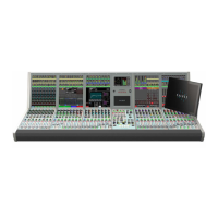
Meter Grid Configuration
Select >Show Settings>Meter Layout,
from the buttons on the left hand side.
The Meter Setup screen shows thumbnail
images of all available TFT panels in a
column down the left hand side of the
screen. Touch to select the TFT panel to
edit and the main screen grid is populated
with the settings for this panel.
The buttons along the top of the main
meter setup window allow control of the
configuration. Selecting the ‘Grid’ tab
subdivides the window to show the current
layout see Fig 3.
FIG 2 - EXAMPLE LAYOUT GRID
FIG 3 - GRID CONFIGURATION
FIG 1 - EXAMPLE TFT METER LAYOUT