Getting Signals into Apollo
58 APOLLO
Digital Broadcast Production Console
ALLOCATING SIGNAL PATHS TO FADERS
A path is a generic term that refers
to a DSP process in the system. A
signal present at an input port must
be routed to a Channel path in order
for it to be processed, routed, then
sent back out of the system.
Running at 48KHz, Apollo has 1020
mono channel paths available. The user
is free to configure this pool of mono
resources as required. Simply assigning
any path type to a fader (mono, stereo
or surround) automatically allocates the
required number of DSP resources from
the pool of 1020. A mono channel path
uses a single DSP resource, a stereo
channel path uses two mono resources,
and a 5.1 channel path uses six mono
resources.
Assigning channels to faders
For a path to be directly controlled,
processed and routed, it must be attached
to a fader on the surface. Input Channels
and Output buses need to be patched to
a path in order for audio to pass through
the system. This is detailed in the
‘Getting Signal into Apollo’ section of this
document.
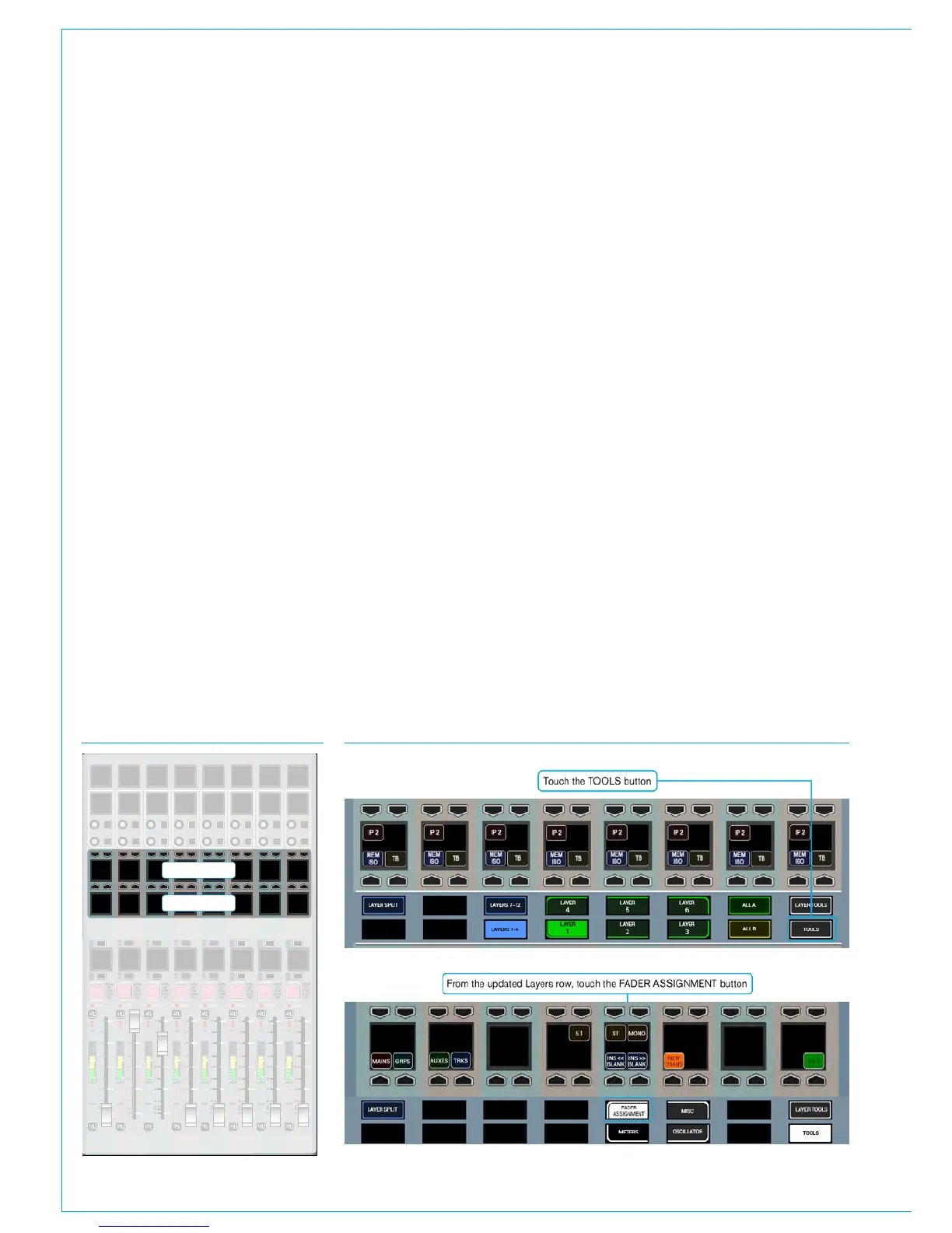
Select TOOLS>FADER ASSIGNMENT
from the Layers row, as shown in Fig 2
and then NEW CHANS from the row
above to display the input channel types
available for allocation.
Select a blank fader by pressing its’
assign button above (A layer) or below (B
layer) its label display to highlight it blue
and make it the currently assigned path
- the focus of assignable controls. From
the New Chans menu, select a width of
input channel to allocate to the fader – 5.1
surround, stereo or mono. On releasing
the button, a DSP input channel of the
chosen width is instantly allocated to the
assigned fader and its label display is
updated accordingly.
Paths of the same width can quickly be
assigned to multiple faders by holding a
channel width button down whilst then
selecting the assign buttons of the blank
faders to allocate the channels to.
Once a fader has a signal path on it, the
path type or width cannot be changed,
the path must first be removed before a
different path can be allocated.
When assigning input channels to paths in
this way, a new input channel is allocated
to each fader from the available DSP
resource pool. DSP resources are quoted
in mono channel legs. When a stereo
channel is allocated, 2 mono paths are
used from the resource pool, and 6 are
used to create a 5.1 surround channel.
Assigning buses to faders
Main Output buses and audio sub-group
buses that have been configured can
also be allocated to faders if required.
Selecting Mains or Groups from the
TOOLS>FADER ASSIGNMENT menu
displays the relevant bus types that are
available. If more groups are available
than can be displayed across the panel,
buttons will be present to allow the view to
page through the different groups.
Selecting a Main or group will allocate
that DSP path to the currently assigned
fader as long as the fader does not
already have a path allocated. Main
output paths can also be allocated to the
faders on the dedicated monitor panel
if the full-featured version with faders is
fitted. When allocating to these faders,
FIG 1 - ROW LOCATIONS FIG 2 - ASSIGN FADERS VIEWS ON THE SETUP ROW
20
+
-
PEAK
40
0
60
50
5
20
30
10
5
0
10
0
20
10
10
START
ON
0
STRIP
FDR
CUT/ON
AUTOM
EXT
CUT
STRIP
FDR
CUT/ON
AUTOM
EXT
CUT
STRIP
FDR
CUT/ON
AUTOM
EXT
CUT
STRIP
FDR
CUT/ON
AUTOM
EXT
CUT
STRIP
FDR
CUT/ON
AUTOM
EXT
CUT
STRIP
FDR
CUT/ON
AUTOM
EXT
CUT
STRIP
FDR
CUT/ON
AUTOM
EXT
CUT
STRIP
FDR
CUT/ON
AUTOM
EXT
CUT
20
+
-
PEAK
40
0
60
50
5
20
30
10
5
0
10
0
20
10
10
START
ON
0
20
+
-
PEAK
40
0
60
50
5
20
30
10
5
0
10
0
20
10
10
START
ON
0
20
+
-
PEAK
40
0
60
50
5
20
30
10
5
0
10
0
20
10
10
START
ON
0
20
+
-
PEAK
40
0
60
50
5
20
30
10
5
0
10
0
20
10
10
START
ON
0
20
+
-
PEAK
40
0
60
50
5
20
30
10
5
0
10
0
20
10
10
START
ON
0
20
+
-
PEAK
40
0
60
50
5
20
30
10
5
0
10
0
20
10
10
START
ON
0
20
+
-
PEAK
AFL
PFL
AFL
PFL
AFL
PFL
AFL
PFL
AFL
PFL
AFL
PFL
AFL
PFL
AFL
PFL
40
0
60
50
5
20
30
10
5
0
10
0
20
10
10
START
ON
0
4
8
12
16
20
24
42
E
C
60
DYN 2
DYN 1
O/P 1
PATH
4
8
12
16
20
24
42
E
C
60
DYN 2
DYN 1
O/P 1
PATH
4
8
12
16
20
24
42
E
C
60
DYN 2
DYN 1
O/P 1
PATH
4
8
12
16
20
24
42
E
C
60
DYN 2
DYN 1
O/P 1
PATH
4
8
12
16
20
24
42
E
C
60
DYN 2
DYN 1
O/P 1
PATH
4
8
12
16
20
24
42
E
C
60
DYN 2
DYN 1
O/P 1
PATH
4
8
12
16
20
24
42
E
C
60
DYN 2
DYN 1
O/P 1
PATH
4
8
12
16
20
24
42
E
C
60
DYN 2
DYN 1
O/P 1
PATH
MR
SL
MR
SL
MR
SL
MR
SL
MR
SL
MR
SL
MR
SL
MR
SL
MR
SL
MR
SL
MR
SL
MR
SL
MR
SL
MR
SL
CUT
CUT
CUT
CUT
CUT
CUT
CUT CUT
MR
SL
MR
SL
Layers Row
Functions Row