CALREC Putting Sound in the Picture 87
DYNAMICS 1
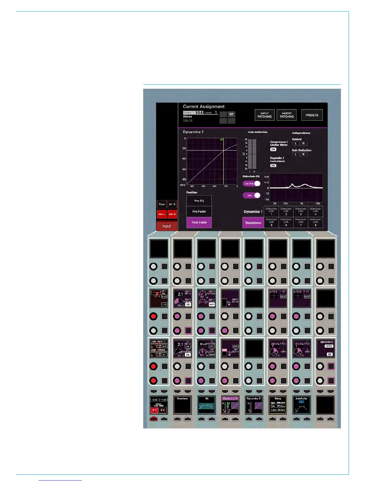
FIG 1 - DYN CONTROLS ON THE PROCESSING-DYN 1 ASSIGN MODE LAYOUTEvery channel / group / main path
has to two dedicated dynamics
processing units that are always
available to them. Dynamics 1 shown
right provides a Compressor / Limiter
and Expander or Gate.
Dynamics controls
The dynamics controls and related
displays are all located in the
PROCESSING-DYNAMICS 1 panel
mode, as shown in Fig 1.
Dynamics controls and displays
are all colour-coded purple. The
controls are arranged in 3 blocks:-
Compressor /Limiter controls for ON,
Threshold, Ratio, Attack, Recovery and
Gain Make-up. Expander or Gate controls
for ON, Threshold, Ratio, Attack, Recovery
and Depth and 2 bands of Dynamics
sidechain EQ controls for Gain, Frequency
and Q / Response types.
The TFT screen displays a graph of
input level versus output level along with
switchable gain reduction meters, the
position of the Dynamics 1 processing in
the Signal Path and switches for control
and gain reduction independence of
legs for stereo and 5.1 path legs. With
SCEQ selected on the TFT screen, it also
displays the EQ curve for the dynamics 1
side-chain. Also shown are the 8 Dyn
Links selector which this path can be
linked to or can be left as No Link for
independent operation .
Both dynamics 1 & 2 can be used
as limiters simply by switching the
compressor in and setting the ratio to
the maximum of 50:1. At this setting,
the input has to increase by 50dB above
the threshold in order for the output to
increase by a negligible 1dB - the signal is
effectively being limited.