CALREC Putting Sound in the Picture 67
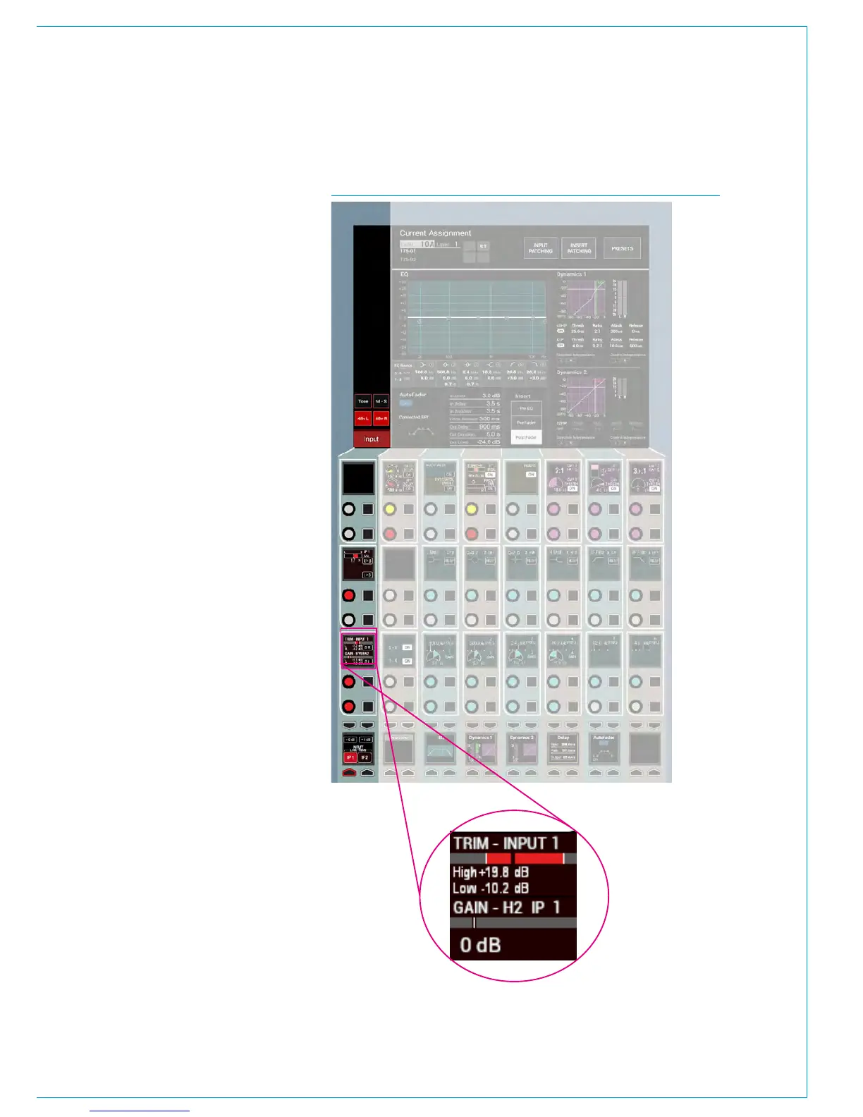
FIG 1 - INPUT CONTROLS COLUMN ON PROCESSING OVERVIEW
INPUT CONTROLS
Once a path has been assigned to a
fader, certain options are available to
control the input signal.
Depending on the operating mode, the
controls may be accessible in various
locations on the surface. As the controls
available in Wilds mode are very flexible
and may have been customised by the
user, this section will detail the controls
available on a panel in Assign Mode
using any of the standard PROCESSING
layouts.
Fig 1 shows the layout of input controls
in the PROCESSING - Overview Assign
mode layout.
Inputs 1 and 2
Each input channel can be quickly
switched between two inputs using
the INPUT 1 and INPUT 2 selection
buttons. A common use for input 2 is for
backup microphones, allowing them to
be easily available, using the same fader,
processing and routing as when using the
primary microphone on Input .
Mic/Line gain
The gain of any connected mic/line input
can be adjusted with this control. The
gain range varies from +78 to -18 dB.
This gain control alters the gain at the
input port in a Hydra2 I/O unit and will
only be available to the owner of that port.
Port ownership is discussed in the Input
Sources section of this document.
If the gain is not the same on all legs of a
channel then the gain display will show the
highest and lowest value, as highlighted in
Fig 1’s exploded view. (Shown Right)
±6dB coarse gain
This control allows coarse gain
adjustments to be made to the mic/line
input gain. Pressing the + or - buttons
will boost or attenuate the gain by 6dB
respectively.