CALREC Putting Sound in the Picture 93
DELAY
Delay can be inserted into the signal
path in the following ways:
• Input delay - up to 2.73s available per
input path from a pool of 256 mono
legs (e.g when assigning to a 5.1
signal, 6 of the 256 mono legs will be
used). This can be assigned from the
PROCESSING-DELAY panel
• Path delay - up to 2.73s always
available for all paths from the
PROCESSING-DELAY panel which
can be placed, pre-eq, pre-fader or post
fader.
• Output delay - up to 2.73s available per
path from a pool of 256 mono legs this
delay can be applied to Direct Outputs,
Mains, Tracks and Auxs when assigned
to the surface from the Bus Output
panel.
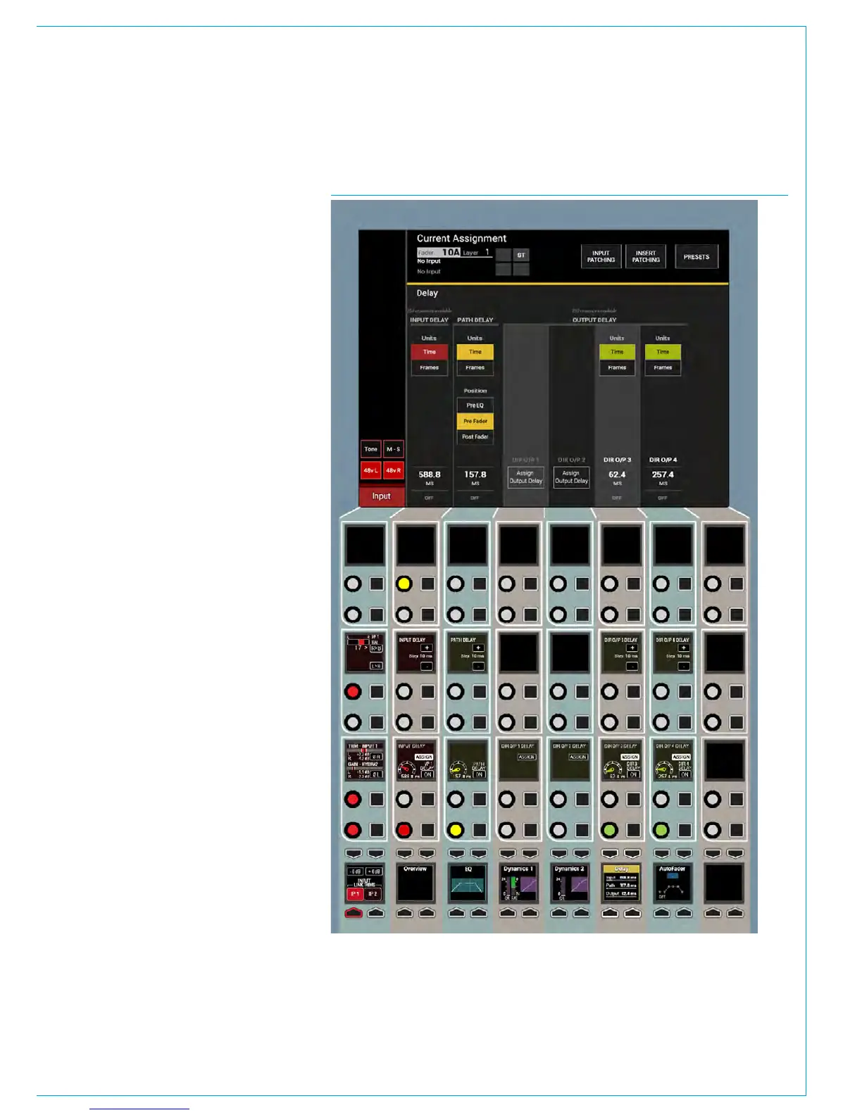
Note that Input, Path and Output
delay can be used individually or in
combination. See Fig 1.
Assignable Delay at different
sample rates.
From version 8.0 the desk can be
configured to operate at different sample
rates such as 48kHz & 96kHz.
At the higher sample rate the pool size for
input and output delay is halved, meaning
that the pool of 256 mono legs worth of
delay becomes 128 mono legs of delay,
however the amount of delay per leg
remains unchanged at 2.73s.
Individual Assignable Delay
To apply an assignable delay, select the
PROCESSING-DELAY panel mode and
press the appropriate assign button
(Input or Output) on the lower control row.
Note that for direct outputs the outputs
themselves have to be assigned first
before delay can be assigned to them.
Individual Path Delay
The Path Delay control is always available
on all Channel, Group, Main, Aux or Track
paths and can be placed, pre-eq, pre-fader
or post fader using the Position buttons
in the PATH DELAY column on the TFT
screen. Working from the top of the
FIG 1 - DELAY CONTROLS ON THE PROCESSING-DELAY ASSIGN MODE LAYOUT
position block, the TFT shows a three-
state button cell which allows the signal
chain positioning to be changed between
PRE EQ, PRE FADER and POST FADER.
As shown in “Channel Signal Flow” on
page 84, path delay is inserted at the
end of the processing block, after insert,
dynamics 1 and dynamics 2. The pre EQ
and post fader sends are situated after
the respective path delay, but it is worth
noting that the pre fader send is situated
prior to the pre fader path delay.