External Interfacing
190 APOLLO
Digital Broadcast Production Console
GPIO
Opto isolated General Purpose
Inputs can be configured to allow the
console to respond to external control
signals. Conversely, the console can
output control signals via relays to
control external equipment.
Assigning GPIs
>Hydra2 Settings>GPI shows the
available GPI opto inputs listed on the left
hand side of this screen. ‘Filter Inputs’
allows rapid access to specific Hydra2 I/O
boxes with GPIO connections.
The console functions which can be
controlled by the optos are shown on
the right hand side of the screen. Select
an opto input and a console function
and touch the ‘Patch’ button to make a
connection between the two.
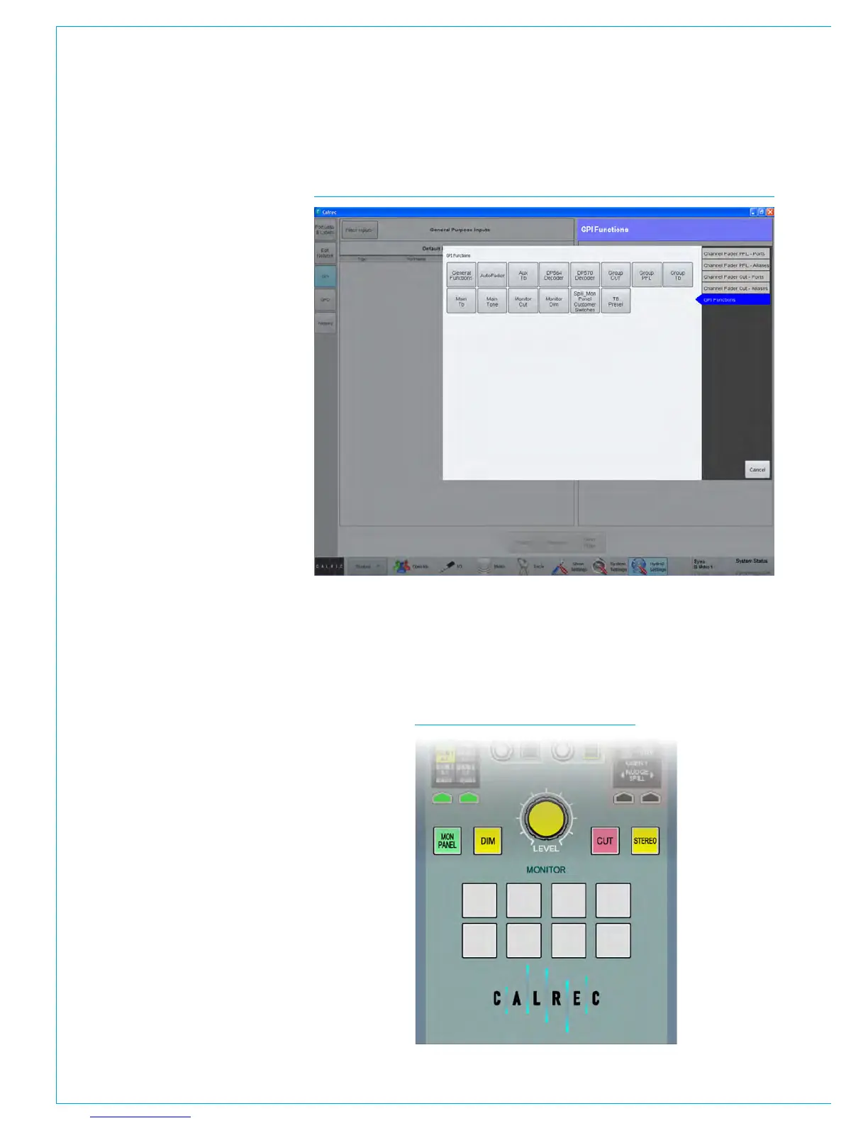
GPI functions
The list of GPI input ports can be filtered
using the ‘Filter Inputs’ button above
the ports list. This will bring up a popup
window showing the available functions
grouped into 5 sections as shown in Fig 1.
To set a GPI to control a channel specific
function, either PFL or CUT, select one of
the first four options for physical ports or
Aliases. Then, from the resulting button
options, select the correct I/O box for the
port(s) you wish to control. The pop-up
will then close and the GPI functions
window is populated with all ports for the
selected I/O box.
All GPI controllable console functions are
listed within the 5th option: GPI Functions.
Within this option there are several button
selectors for different GPI function types,
for example, TX status (found under the
‘General Functions’ filter), Auto Faders
and a variety of talkback, tone and monitor
functions under the appropriate filter
buttons.
FIG 1 - ASSIGNING GPI OPTOS TO CONSOLE FUNCTIONS SELECTOR
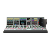
Mon-Spill Panel Customer Switches
In addition to functions that control the console, the eight Customer Switches at the
base of the Monitor/Spill panel (Fig 2 shown below) all have coloured indicators which
can be assigned to be activated from GPIs. This can be used as a method for checking
the correct operation of a relay/opto circuit. Customer Switches can have up to three
different colour states allowing them to provide feedback from three separate GPI
inputs.
FIG 2 - CUSTOMER SWITCHES