CALREC Putting Sound in the Picture 77
TONE / OSCILLATOR CONTROLS
There are many tone injection points
within the Apollo DSP to aid with path
checking and line-up.
Tone can be routed in the following ways:
• To a channel or group fader’s input -
press the fader’s ASSIGN button and
select TONE in the lower left hand
corner of any PROCESSING mode
TFT screen.
• To Track outputs - press the rotary
controller for the required track output
when in the OUTPUTS panel mode to
bring up extra controls including tone
switching, then select TONE>TRACK
• To Aux outputs - press the rotary
controller for the required aux output
when in the OUTPUTS panel mode to
bring up extra controls including tone
switching, then select TONE>AUX
• To Group Outputs - press the rotary
controller for the required group output
when in the OUTPUTS panel mode to
bring up extra controls including tone
switching, then select TONE>GROUP
• To Main outputs - press the rotary
controller for the required main output
when in the OUTPUTS panel mode to
bring up extra controls including tone
switching, then select TONE>MAIN
• To Main outputs from the 4 faders on
the monitor panel - If main outputs
are assigned to these faders, and the
panel is not in downmix or spill levels
mode, the button just above each fader
becomes a tone selector.
Changing the mode of panels or the
assigned focus by selecting a different
fader or output bus does not clear the
tone. Tone will remain until deselected or
globally cleared.
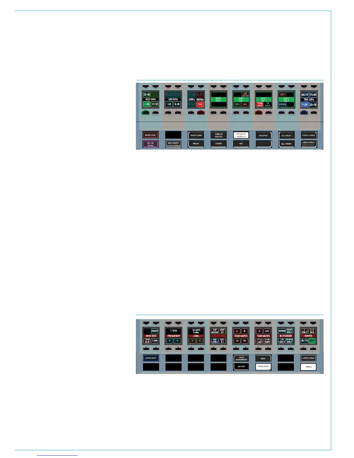
FIG 2 - OSCILLATOR CONTROLS
The Oscillator functions provide
control over internal tone parameters
and allow the option to override the
internal tone generator with external
or ‘house’ tone.
These controls can be accessed from any
fader panel by pressing TOOLS and then
OSCILLATOR on any fader panel’s Modes
row. The oscillator controls will then be
displayed in the Functions row above, as
shown in the image below.
Oscillator Parameters
The Functions row provides controls to
adjust the internal oscillator’s level and
frequency, including a repeating tone
sweep function and mute options for each
leg of the accessed path:
• Frequency ranges cover the band from
20Hz to 20kHz.
• Level is displayed in both dBFS and
dBU.
• The oscillator sweep is stepped and
runs from 20Hz to 20kHz.
• The < and > buttons allow you to
change the direction of the sweep.
• Pressing and holding ‘1KHz’ or ‘Ref
Level’ will reset to the default values.
Note, the default level value is intended
to match your regional or chosen running
levels and line-ups, e.g for the US, the
default lineup setting is -20dBFS/+4dBU
whereas for the UK it is -18dBFS/0dBU.
If your line-up levels are not as expected
please contact your engineering support
or Calrec support at support@calrec.com.
FIG 1 - ASSIGNING TONE TO A BUS OUTPUT
• Panel in Outputs mode shown after Aux 1 rotary control press